
3 ITEMSVIEW CART


Total: 440.00
Expert Support
Full Speed
100% Working
100 USD
Contents:
Introduction
General Information
Safety
General References
Diagnostic Philosophy
Diagnostic Trouble Codes
Dry Spinner Spreader – DRC – Diagnostic Trouble Codes
ASM – Diagnostic Trouble Codes
ATC – Diagnostic Trouble Codes
BH1 – Diagnostic Trouble Codes
BH2 – Diagnostic Trouble Codes
CC1 – Diagnostic Trouble Codes
CC2 – Diagnostic Trouble Codes
CLC – Diagnostic Trouble Codes
CRU – Diagnostic Trouble Codes
CSM – Diagnostic Trouble Codes
ECU – Level 24 – Diagnostic Trouble Codes
ECU – Level 33- Diagnostic Trouble Codes
EIC – Diagnostic Trouble Codes
FCC – Diagnostic Trouble Codes
iTC – Diagnostic Trouble Codes
JDL – Diagnostic Trouble Codes
JL2 – Diagnostic Trouble Codes
LCC – Diagnostic Trouble Codes
OIC – Diagnostic Trouble Codes
PDU – Diagnostic Trouble Codes
RG3 – Diagnostic Trouble Codes
RLC – Diagnostic Trouble Codes
SR1 – Diagnostic Trouble Codes
SR2 – Diagnostic Trouble Codes
TEC – Diagnostic Trouble Codes
TEI – Diagnostic Trouble Codes
VLC – Diagnostic Trouble Codes
VTi – Diagnostic Trouble Codes
WDS – Diagnostic Trouble Codes
XMC – Diagnostic Trouble Codes
XSC – Diagnostic Trouble Codes
Observable Symptom and System Diagnostics
Electrical
Electronic Control Units
Drivetrain
Steering and Brakes
Hydraulics and Pneumatics
Solution System
Heating, Ventilation, and Air Conditioning
Dry Application System – Electrical
Dry Application System – Control Unit
Dry Application System – Hydraulics
Engine
General Information
Engine Systems
Fuel, Air Intake, Exhaust and Cooling
General Information
Fuel, Air Intake, Exhaust and Cooling Systems
Electrical
General Information
Operation and Preliminary Checks
Theory of Operation-Application System
Theory of Operation-Boom
Theory of Operation-Cab
Theory of Operation-CAN Bus
Theory of Operation-Engine
Theory of Operation-GreenStar
Theory of Operation-Hydraulic Electrical
Theory of Operation-Lighting
Theory of Operation-Power Train
Theory of Operation – Starting-Charging-Power Distribution
Theory of Operation – AutoTrac RowSense and AutoTrac Vision
Schematic-Application System
Schematic-Boom
Schematic-Cab
Schematic-CAN Bus
Schematic-Engine
Schematic-GreenStar
Schematic-Hydraulic Electrical
Schematic-Lighting
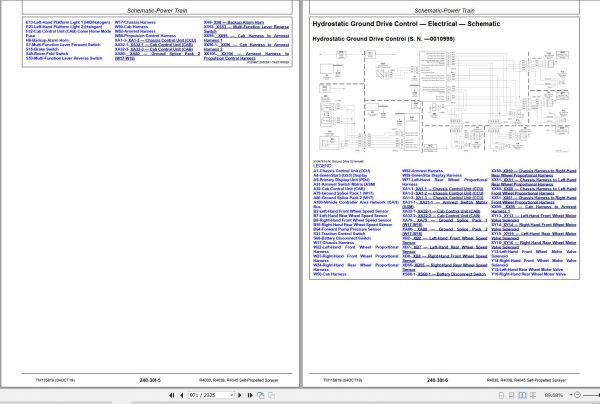
Schematic-Power Train
Schematic-Starting, Charging and Power Distribution
Schematic – AutoTrac RowSense and AutoTrac Vision
Diagnostics-Application System
Diagnostics-Boom
Diagnostics-Cab
Diagnostics-CAN Bus
Diagnostics – Engine
Diagnostics-GreenStar
Diagnostics-Hydraulic Electrical
Diagnostics-Lighting
Diagnostics-Power Train
Diagnostics-Starting, Charging and Power Distribution
Diagnostics-AutoTrac RowSense and AutoTrac Vision
Electronic Control Units
General Information
Control Unit Addresses
Programming Electronic Control Units
Theory of Operation
Schematic
Diagnostics
Electrical Component Information
Electrical Assemblies
Sensors
Lights
Fuses
Charging
Monitoring Devices
Relays
Motors
Resistors
Switches
Diodes
Interconnects and Ground Points
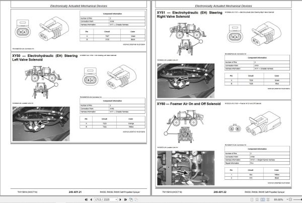
Electronically Actuated Mechanical Devices
Drivetrain
General Information
Theory of Operation
Schematic
Diagnostic Tests and Adjustments
Drivetrain Component Information
Drivetrain Component Information
Steering
Theory of Operation
Schematic
Diagnostic Tests and Adjustments
Park Brake
Theory of Operation
Schematic
Diagnostic Tests and Adjustments
Service Brakes
Theory of Operation
Schematic
Diagnostic Tests and Adjustments
Tread Adjust
Test Procedures and Adjustments
Theory of Operation
Schematic
Component Information
Component Information
Hydraulics
General Information
Test Procedures and Adjustments
Theory of Operation-Application System
Theory of Operation-Basic Hydraulic System
Theory of Operation-Boom
Schematic-Application System
Schematic-Basic Hydraulic System
Schematic-Boom
Diagnostics-Application System
Diagnostics-Basic Hydraulic System
Diagnostics-Boom
Pneumatics
Test Procedures and Adjustments
Theory of Operation
Schematic
Diagnostic
Hydraulics Component Information
Accumulators
Sensors or Gauges
Cylinder, Actuator, or Piston
Check Valve
Filter
Valve Block, Assembly, or Gearcase
Oil Cooler
Motor
Orifice
Pump
Reservoir
Valve
Coupler or Diagnostic Receptacle
Solenoid Valve
Solution System
Test Procedures and Adjustments
Theory of Operation
Schematic
Diagnostics
Solution System Component Information
General Information
Accumulators
Sensors
Check Valves
Filters
Valve Block, Assembly, or Gearcase
Motors
Orifices
Pumps
Reservoirs
Valves
Diagnostic Receptacle or Coupler
Solenoids
Heating, Ventilation, and Air Conditioning System
General Information
Operational and Preliminary Checks
Theory of Operation – HVAC
Schematic – HVAC
Diagnostics – HVAC
Special Tools
Service Tools and Kits
AutoTrac RowSense and AutoTrac Vision
Theory of Operation
Schematic
Diagnostic
AutoTrac RowSense and Vision – Electrical Component Information
Electrical Assemblies
Sensors
Fuses
Relays
Interconnects and Ground Points
Dry Spinner Spreader – Electrical
General Information
Application System Theory of Operation
CAN Bus Theory of Operation
Lighting Theory of Operation
Application System Schematic
CAN Bus Schematic
Lighting Schematic
Application System Diagnostic
CAN Bus Diagnostic
Lighting Diagnostic
Diagnostic Tests and Adjustments
Dry Spinner Spreader – Electronic Control Units
General Information
Theory of Operation
Schematic
Diagnostic
Diagnostic Tests and Adjustments
DRC Addresses
Dry Spinner Spreader – Electrical Component Information
Electrical Assemblies
Sensors
Lights
Motors
Interconnects and Ground Points
Electronically Actuated Mechanical Devices
Dry Spinner Spreader – Hydraulic
General Information
Tests Procedures and Adjustments
Theory of Operation
Schematic
Diagnostic
Dry Spinner Spreader – Hydraulic Component Information
Motors
Valves
Solenoid Valve
Page Number
REALEASE :
13.05.2022

REALEASE :
12.21.2021
REALEASE :
12.21.2021

REALEASE :
14.04.2022
REALEASE :
14.04.2022
REALEASE :
13.05.2022

REALEASE :
10.09.2021
REALEASE :
10.09.2021

REALEASE :
12.07.2021
REALEASE :
12.07.2021

REALEASE :
REALEASE :
REALEASE :
13.05.2022
 Automotive - Heavy Equipment - Truck & Bus - Forklift - Crane

