
1 ITEMVIEW CART

Total: 50.00

Expert Support
Full Speed
100% Working
150 USD
Contents:
cop-intro_LANDINI
Einleitung
Verantwortung
Zweck des Handbuchs
Copyright
Allgemeines Inhaltsverzeichnis
1001
Sicherheit
2
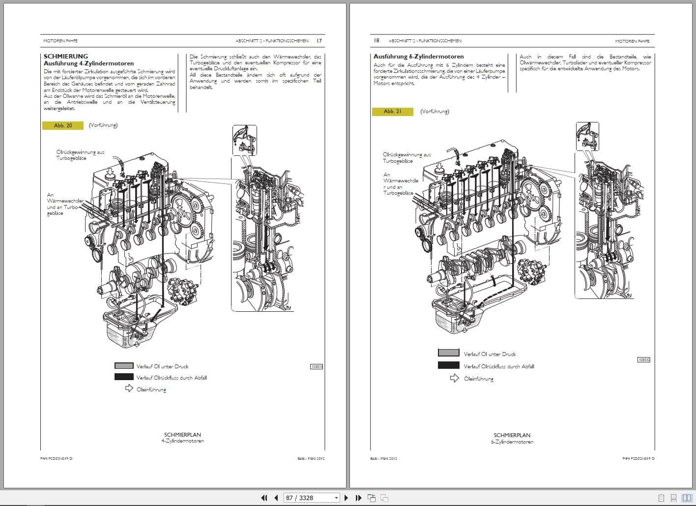
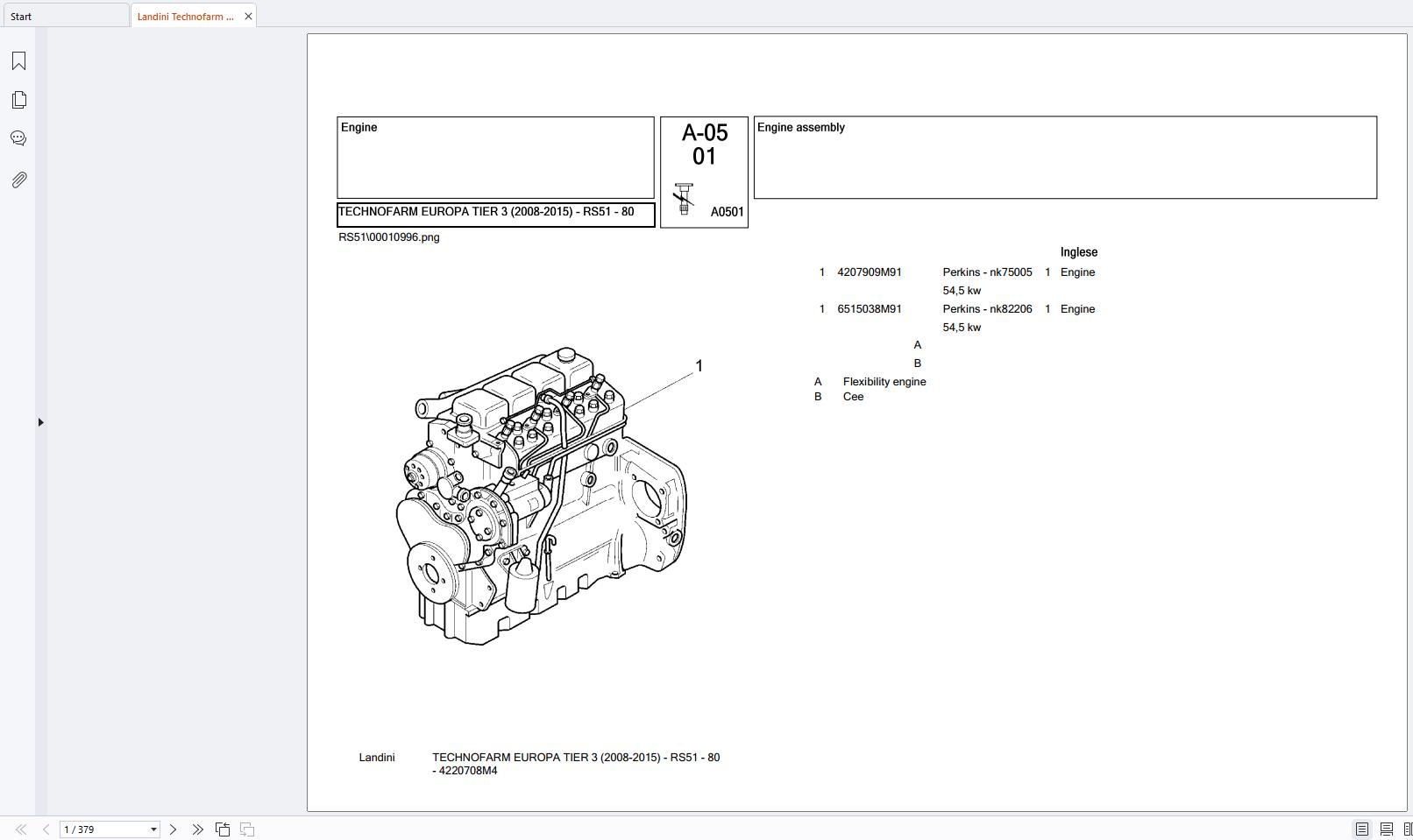
Motor
2002
Abgas-Nachbehandlungssystem
3005
Tanks
4001
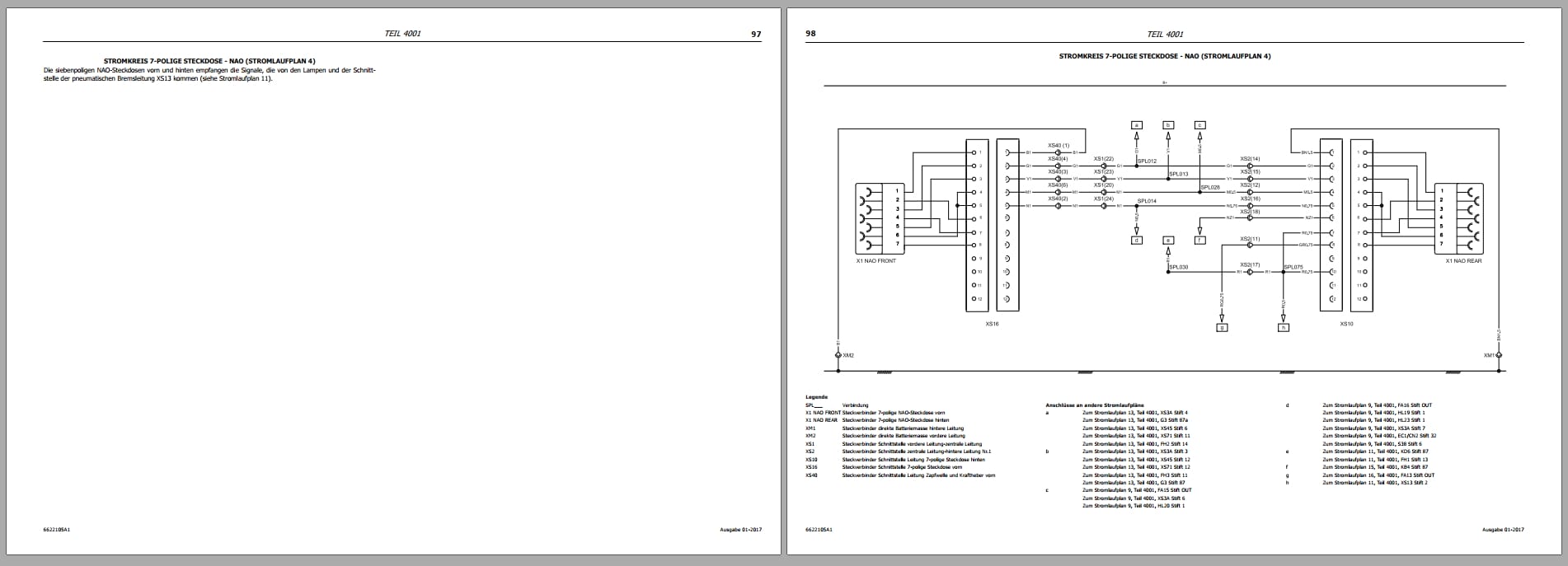
Beschreibungen – Stromlaufpläne – Steckverbinder
4002
Konfiguration der Instrumententafel
5001
Lenksäule und Hydrolenkung
5002_STD
Standard-Hydrolenkung
5002_ELET
Elektronische Hydrolenkung
6
Getriebe – Torsionsdämpfer
6_01_DE_WSM_ZF_T-7200
ZF- SCHLEPPERTRIEBWERK T-7200 PVS
6_02_5871.966.101 de_CVT
ZF – HINTERACHSE T-7200 TRA 16/TRA 20
6_03_CA270093
6_04_CA270068_Lan
Indice
A INFORMAZIONI GENERALI
A General information
B Safety instructions
B INFORMAZIONI SULLA SICUREZZA
C CARATTERISTICHE GENERALI
C General specifications
D OPERAzioni di SMONTAGGIO E montaggio
D Disassembly and assembly operations
E SUSPENSION CONTROL UNIT
E GRUPPO CONTROLLO SOSPENSIONI
F Troubleshooting
F RICERCA GUASTI
G Special tools
G ATTREZZATURE SPECIALI
7
Bremsen Funktionsweise
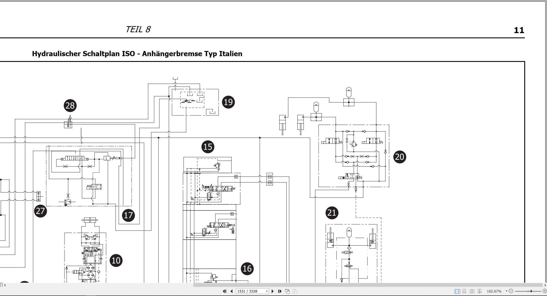
8_PIST
Hydraulikkomponenten Version mit Kolbenpumpe Funktionsweise
8_INGR
Hydraulikkomponenten Version mit Zahnradpumpe Funktionsweise
8001_PIST
Fehlersuche in der hydraulischen Anlage – Kolbenpumpe
8001_INGR
Fehlersuche in der hydraulischen Anlage – Zahnradpumpe
8003
Kolbenpumpe
8004
Zahnradpumpe
8007
Frontkraftheber und Frontzapfwelle
9001
Einstellung der Pedale, Hebel und Schalter
9005
Fahrersitz
10
Steuerungen – CAN Leitung Funktionsweise
10001
Steuerung der Zwischenachsventile Beschreibungen, Stromlaufpläne
10002
Steuerung von Kraftheber und Zusatzventilen Kalibrierung, Fehlercodes, Fehlersuche, Beschreibungen, Stromlaufpläne
10003
Steuerung gefederte Achse Kalibrierung, Fehlercodes, Fehlersuche, Beschreibungen, Stromlaufpläne
10005
Motorsteuerung Fehlercodes, Fehlersuche, Beschreibungen, Stromlaufpläne
10006
GETRIEBESTEUERUNG Kalibrierung, Fehlercodes, Fehlersuche, Beschreibungen, Stromlaufpläne
10008
Steuerung der Klimaanlage Fehlercodes, Fehlersuche, Beschreibungen, Stromlaufpläne
10009
Instrumentensteuerung Kalibrierung, Fehlercodes, Fehlersuche, Beschreibungen, Stromlaufpläne
10011
Steuerung der Kabine und der gefederten Achse Kalibrierung, Fehlercodes, Fehlersuche, Beschreibungen, Stromlaufpläne
10012
Steuerung der Schnittstelle CAN/ISO Beschreibungen, Stromlaufpläne
10013
ISOBUS-Steuerung und satellitengestütztes Lenksystem Fehlercodes, Fehlersuche, Beschreibungen, Stromlaufpläne
Contents:
cop-intro_LANDINI
Introduction
Responsibility
Purpose of the Manual
Copyright
General Table of Contents
1001
Safety
2
Engine
2002
Exhaust Aftertreatment System
3005
Tanks
4001
Descriptions – Wiring Diagrams – Connectors
4002
Instrument Panel Configuration
5001
Steering Column and Power Steering
5002_STD
Standard Power Steering
5002_ELET
Electronic Power Steering
6
Transmission – Torsion Damper
6_01_EN_WSM_ZF_T-7200
ZF TRACTOR TRANSMISSION T-7200 PVS
6_02_5871.966.101 en_CVT
ZF REAR AXLE T-7200 TRA 16/TRA 20
6_03_CA270093
6_04_CA270068_Lan
Index
A GENERAL INFORMATION
A General information
B Safety instructions
B SAFETY INFORMATION
C GENERAL CHARACTERISTICS
C General specifications
D Disassembly and assembly operations
D Disassembly and assembly operations
E SUSPENSION CONTROL UNIT
E SUSPENSION CONTROL UNIT
F Troubleshooting
F Troubleshooting
G Special tools
G SPECIAL TOOLS
7
Brakes Function
8_PIST
Hydraulic components version with piston pump Function
8_INGR
Hydraulic components version with gear pump Function
8001_PIST
Troubleshooting the hydraulic system – piston pump
8001_INGR
Troubleshooting the hydraulic system – gear pump
8003
Piston Pump
8004
Gear Pump
8007
Front Hitch and Front PTO
9001
Adjusting Pedals, Levers, and Switches
9005
Driver’s Seat
10
Controls – CAN Line Functionality
10001
Mid-Axle Valve Control Descriptions, Circuit Diagrams
10002
Hitch and Auxiliary Valve Control Calibration, Error Codes, Troubleshooting, Descriptions, Circuit Diagrams
10003
Suspended Axle Control Calibration, Error Codes, Troubleshooting, Descriptions, Circuit Diagrams
10005
Engine Control Error Codes, Troubleshooting, Descriptions, Circuit Diagrams
10006
Transmission Control Calibration, Error Codes, Troubleshooting, Descriptions, Circuit Diagrams
10008
Air Conditioning Control Error Codes, Troubleshooting, Descriptions, Circuit Diagrams
10009
Instrument Control Calibration, Error Codes, Troubleshooting, Descriptions, Circuit Diagrams
10011
Cab and suspended axle control: Calibration, error codes, troubleshooting, descriptions, and wiring diagrams
10012
CAN/ISO interface control: Descriptions and wiring diagrams
10013
ISOBUS control and satellite-based guidance system: Error codes, troubleshooting, descriptions, and wiring diagrams

REALEASE :
REALEASE :

REALEASE :
REALEASE :

REALEASE :
REALEASE :

REALEASE :
REALEASE :

REALEASE :
REALEASE :

REALEASE :
REALEASE :

REALEASE :
REALEASE :
REALEASE :
REALEASE :
 Automotive - Heavy Equipment - Truck & Bus - Forklift - Crane