
5 ITEMSVIEW CART


Total: 390.00
Expert Support
Full Speed
100% Working
30 USD
Contents:
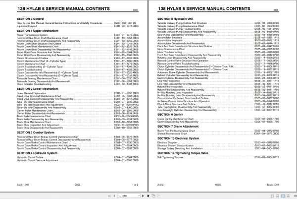
SECTION 0 General
How To Use This Manual, General Service Instructions, And Safety Procedures SM00-000-001.00
ES00-03-0071.0R0S : Equipment Layout
SECTION 1 Upper Mechanism
ES01-01-0079.0R0S : Power Transmission System
ES01-10-2051.1R0S : Front And Rear Drum Shaft Maintenance Chart
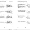
ES01-10-6068.0R0S : Front And Rear Drum Shaft Disassembly And Reassembly
ES01-12-0041.0R0S : Fourth Drum Shaft Structure And Outline
ES01-12-2035.0R0S : Fourth Drum Shaft Maintenance Chart
ES01-12-6048.0R0S : Fourth Drum Shaft Disassembly And Reassembly
ES01-15-0064.0R1S : Boom Hoist Drum Structure And Outline
ES01-15-6066.0R0S : Boom Hoist Drum Disassembly And Reassembly
ES01-17-0059.0R0S : Clutch Structure And Outline
ES01-17-2080.0R0S : Clutch Maintenance Chart (2-Cylinder Type)
ES01-17-2073.0R0S : Clutch Maintenance Chart
ES01-17-4009.0R0S : Clutch Troubleshooting (2-Cylinder Type)
ES01-17-4023.0R0S : Clutch Troubleshooting
ES01-17-6025.4R0S : Clutch Disassembly And Reassembly (1-Cylinder Type)
ES01-17-6032.1R0S : Clutch Disassembly And Reassembly (2-Cylinder Type)
ES01-30-2030.5R0S : Turntable Bearing Maintenance Chart
ES01-30-6054.0R0S : Turntable Bearing Disassembly And Reassembly
ES01-50-4001.1R0S : Drum Indicator Troubleshooting
SECTION 2 Lower Mechanism
ES02-01-0050.1R0S : Lower General Explanation
ES02-05-2061.0R0S : Tread Drive Sprocket Maintenance Chart
ES02-05-6047.0R0S : Tread Drive Sprocket Disassembly And Reassembly
ES02-07-2032.0R0S : Take-Up Idler Maintenance Chart
ES02-07-5045.0R0G : Take-Up Idler Inspection And Adjustment
ES02-07-6060.0R0S : Take-Up Idler Disassembly And Reassembly
ES02-08-2059.0R0S : Carrier Roller Maintenance Chart
ES02-08-6034.0R0S : Carrier Roller Disassembly And Reassembly
ES02-09-2049.0R0G : Track Roller Maintenance Chart
ES02-09-6034.0R0S : Track Roller Disassembly And Reassembly
ES02-10-2053.0R2S : Track Shoe Maintenance Chart
ES02-10-5049.0R0G : Track Shoe Inspection And Adjustment
ES02-10-6059.0R0S : Track Shoe Disassembly And Reassembly
SECTION 3 Control System
ES03-05-2076.0R0S : Front And Rear Drum Brakes Control Maintenance Chart
ES03-05-6077.0R0S : Front And Rear Drum Brakes Control Disassembly And Reassembly
ES03-07-2036.0R0S : Fourth Drum Brake Control Maintenance Chart
ES03-07-5034.0R0S : Fourth Drum Brake Control Inspection And Adjustment
ES03-07-6033.0R0S : Fourth Drum Brake Control Disassembly And Reassembly
SECTION 4 Hydraulic System
ES04-01-0084.0R0S : Hydraulic Circuit Outline
ES04-01-5085.0R0S : Hydraulic Circuit Pressure Adjustment
SECTION 5 Hydraulic Unit
ES05-02-0065.0R0S : Variable Delivery Pump Outline And Structure
ES05-02-2052.0R0S : Variable Delivery Pump Maintenance Chart
ES05-02-4011.0R0S : Variable Delivery Pump Troubleshooting
ES05-02-6039.0R0S : Variable Delivery Pump Disassembly And Reassembly
ES05-03-6056.0R0S : Gear Pump Disassembly And Reassembly
ES05-05-0035.1R1S : Accumulator Structure
ES05-05-5032.1R1S : Accumulator Inspection
ES05-05-6046.1R1S : Accumulator Disassembly And Reassembly
ES05-09-0047.0R0S : Front And Rear Drum Motor Structure And Outline
ES05-09-2025.0R0S : Motor Maintenance Chart
ES05-09-4025.0R0S : Motor Troubleshooting
ES05-09-6042.0R0S : Front And Rear Drum Motor Disassembly And Reassembly
ES05-14-6029.2R3S : Rotating Joint Disassembly And Reassembly
ES05-17-0035.0R0S : Remote Control Valve Structure And Operation
ES05-17-4028.0R0S : Remote Control Valve Troubleshooting
ES05-18-6006.0R1S : Clutch Cylinder Disassembly And Reassembly (2-Cylinder Type, R.H.)
ES05-18-6073.0R1S : Clutch Cylinder Disassembly And Reassembly (1-Cylinder Type)
ES05-19-6032.1R0S : Automatic Brake Cylinder Disassembly And Reassembly
ES05-23-6038.0R1S : Retract Cylinder Disassembly And Reassembly
ES05-24-6005.0R1S : Gantry Cylinder Disassembly And Reassembly
ES05-30-5061.1R1S : Line Filter Inspection
ES05-30-6061.1R1S : Line Filter Disassembly And Reassembly
ES05-32-5011.0R0S : Return Filter Inspection
ES05-32-6011.1R0S : Return Filter Disassembly And Reassembly
ES05-34-5012.0R1S : 8-Way Rotating Joint Inspection
ES05-34-6012.0R1S : 8-Way Rotating Joint Disassembly And Reassembly
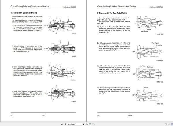
ES05-36-0037.0R0S : Control Valve (2-Series) Structure And Outline
ES05-38-0046.0R0S : 4-Series Control Valve Structure And Operation
ES05-49-0017.0R0S : Check Block Structure And Outline
ES05-57-6052.0R0S : Take-Up Cylinder Disassembly And Reassembly
ES05-59-6054.0R1S : Counterweight Cylinder Disassembly And Reassembly
SECTION 6 Gantry
ES06-01-2035.1R0S : Crane Gantry Maintenance Chart
ES06-01-6035.1R0S : Gantry Disassembly And Reassembly
SECTION 7 Crane Attachment
ES07-08-2032.0R0S : Boom Foot Pin Maintenance Chart
ES07-09-2076.0R0G : Sheave Maintenance Chart
SECTION 13 Electrical System
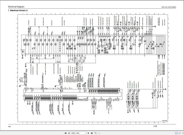
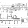
ES13-01-0070.0R0S : Electrical Diagram
ES13-01-9033.0R1S : Electrical System Standardization
ES13-04-5004.0R0S : Storage Battery Servicing And Installation
SECTION 14 Tightening Torque Table
ES14-02-0004.0R1S : Bolt Tightening Torques

REALEASE :
05.03.2021
REALEASE :
05.03.2021

REALEASE :
REALEASE :

REALEASE :
26.01.2021
REALEASE :
26.01.2021

REALEASE :
27.01.2021
REALEASE :
27.01.2021

REALEASE :
REALEASE :

REALEASE :
REALEASE :

REALEASE :
REALEASE :

REALEASE :
REALEASE :
 Automotive - Heavy Equipment - Truck & Bus - Forklift - Crane