
14 ITEMSVIEW CART


Total: 1,720.00


Expert Support
Full Speed
100% Working
30 USD
Contents:
SECTION 0 General
How To Use This Manual, General Service Instructions, And Safety Procedures SM00−000−001.00
ES00−03−0069.0R0S : Equipment Layout
SECTION 1 Upper Mechanism
ES01−01−0070.0R0S : Power Transmission System
ES01−01−2040.0R1S : Gears Maintenance Chart
ES01−10−0034.0R0S : Front And Rear Drum Shaft Structure And Outline
ES01−10−6034.0R0S : Front And Rear Drum Shaft Disassembly And Reassembly
ES01−15−0066.0R1S : Boom Hoist Drum Outline And Structure
ES01−15−6063.0R1S : Boom Hoist Drum Disassembly And Reassembly
Clutch (2−Cylinder Type)
ES01−17−0034.0R0S : Clutch Structure And Outline (2−Cylinder Type)
ES01−17−2034.0R0S : Clutch Maintenance Chart (2−Cylinder Type)
ES01−17−4009.0R0S : Clutch Troubleshooting (2−Cylinder Type)
ES01−17−6034.0R0S : Clutch Disassembly And Reassembly (2−Cylinder Type)
ES01−29−2050.0R0S : Swing Mechanism Maintenance Chart
ES01−30−2030.4R0S : Turntable Bearing Maintenance Chart
ES01−30−5052.0R0S : Turntable Bearing Inspection And Adjustment
ES01−42−2072.0R0S : Drum Maintenance Chart
ES01−50−4001.1R0S : Drum Indicator Troubleshooting
SECTION 2 Lower Mechanism
ES02−01−0051.0R0S : Lower General Explanation
ES02−05−2055.0R0S : Tread Drive Sprocket Maintenance Chart
Take−Up Idler
ES02−07−2059.0R0S : Take−Up Idler Maintenance Chart
ES02−07−5046.0R0S : Take−Up Idler Inspection And Oil Replacement
ES02−07−6053.0R1S : Take−Up Idler Disassembly And Reassembly
ES02−08−2054.0R0S : Carrier Roller Maintenance Chart
ES02−09−2048.0R0S : Track Roller Maintenance Chart
Track Shoe
ES02−10−2053.0R0S : Track Shoe Maintenance Chart
ES02−10−5052.0R0S : Track Shoe Inspection And Adjustment
ES02−10−6052.0R1S : Track Shoe Disassembly And Reassembly
ES02−12−2048.0R0S : Tread Member Maintenance Chart
ES02−21−5050.0R0S : Travel Reduction Gear Case Oil Inspection And Replacement
SECTION 3 Control System
ES03−05−2074.0R0S : Front And Rear Drum Brake Control Maintenance Chart
ES03−05−5068.0R0S : Front And Rear Drum Brakes Control Inspection And Adjustment
ES03−05−6075.0R0S : Front And Rear Drum Brakes Control Disassembly And Reassembly
SECTION 4 Hydraulic System
ES04−01−0082.0R0S : Hydraulic Circuit Outline
ES04−01−5083.0R0S : Hydraulic Circuit Pressure Adjustment
SECTION 5 Hydraulic Unit
ES05−01−0014.0R0S : Hydraulic Unit Equipment Layout
Variable Delivery Pump
ES05−02−0061.0R0S : Variable Delivery Pump Outline And Structure
ES05−02−2052.0R0S : Variable Delivery Pump Maintenance Chart
ES05−02−4009.0R0G : Variable Delivery Pump Troubleshooting
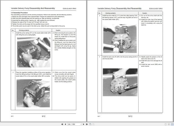
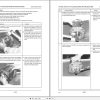
ES05−02−6037.0R0S : Variable Delivery Pump Disassembly And Reassembly
Accumulator
ES05−05−0035.1R1S : Accumulator Structure
ES05−05−5032.1R1S : Accumulator Inspection
ES05−05−6046.1R1S : Accumulator Disassembly And Reassembly
Front And Rear Winch Motor
ES05−09−0034.0R0S : Motor Structure And Outline
ES05−09−2025.0R0S : Motor Maintenance Chart
ES05−09−4011.0R0S : Motor Troubleshooting
ES05−09−6034.0R0S : Motor Disassembly And Reassembly
Boom Hoist Motor
ES05−11−0033.0R0S : Motor Structure And Outline
ES05−11−2025.0R0S : Motor Maintenance Chart
ES05−11−4002.0R0S : Motor Troubleshooting
ES05−11−6029.0R0S : Motor Disassembly And Reassembly
ES05−14−6029.2R3S : Rotating Joint Disassembly And Reassembly
ES05−16−0016.0R1S : Brake Booster Structure And Working
ES05−16−6005.0R1S : Brake Booster Disassembly And Reassembly
ES05−17−0032.0R0S : Remote Control Valve Structure And Operation
ES05−17−4028.0R0S : Remote Control Valve Troubleshooting
ES05−23−4001.1R0S : Hydraulic Cylinder Troubleshooting
ES05−18−6034.0R0S : Clutch Cylinder Disassembly And Reassembly (2−Cylinder Type, Right Hand)
ES05−19−6035.0R0S : Automatic Brake Cylinder Disassembly And Reassembly
ES05−24−6006.0R0S : Gantry Cylinder Disassembly And Reassembly
ES05−30−5061.1R0S : Line Filter Inspection
ES05−30−6061.1R0S : Line Filter Disassembly And Reassembly
ES05−32−5011.0R0S : Return Filter Inspection
ES05−32−6011.0R0S : Return Filter Disassembly And Reassembly
ES05−34−5014.0R1S : 8−Way Rotating Joint Inspection
ES05−35−0055.0R0S : Swing Control Valve Structure And Operation
ES05−37−0051.0R0S : 3−Series Control Valve Structure And Operation
ES05−38−0041.1R0S : 4−Series Control Valve Structure And Operation
ES05−40−0004.0R1S : 6−Series Control Valve Structure And Operation
ES05−57−6048.0R0S : Take−up Cylinder Disassembly And Reassembly
ES05−49−0013.0R1S : Check Block Structure And Outline
ES05−59−6054.0R0S : Counterweight Cylinder Disassembly And Reassembly
SECTION 13 Electrical System
ES13−01−0067.0R0S : Electrical Diagram
ES13−01−9033.0R0S : Electrical System Standardization
ES13−04−5004.0R0S : Storage Battery Servicing And Installation
SECTION 14 Tightening Torque Table
ES14−02−0004.0R0S : Bolt Tightening Torques

REALEASE :
26.01.2021
REALEASE :
26.01.2021

REALEASE :
REALEASE :

REALEASE :
REALEASE :

REALEASE :
REALEASE :

REALEASE :
REALEASE :

REALEASE :
REALEASE :

REALEASE :
05.03.2021
REALEASE :
05.03.2021

REALEASE :
27.01.2021
REALEASE :
27.01.2021
 Automotive - Heavy Equipment - Truck & Bus - Forklift - Crane