
16 ITEMSVIEW CART


Total: 2,195.00

Expert Support
Full Speed
100% Working
15 USD
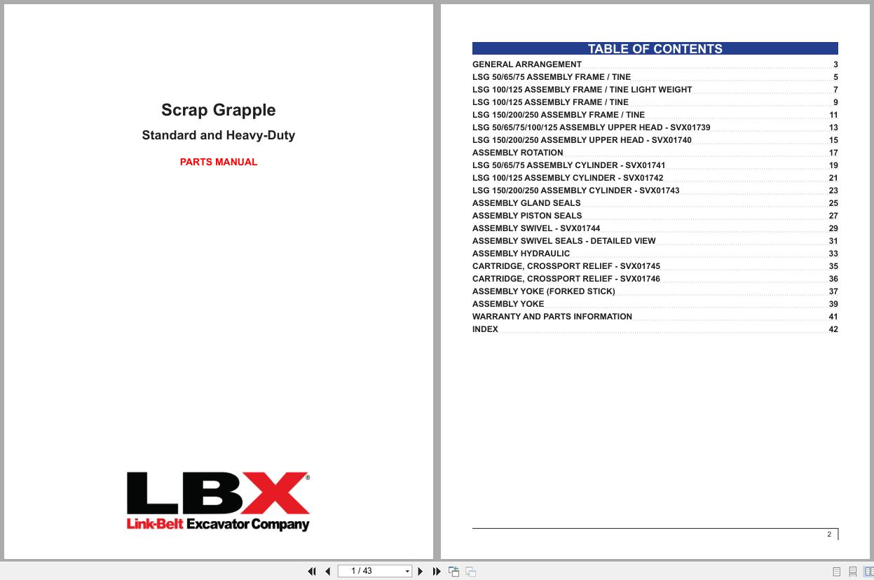
Contents:
Chapter 1 – To The Owner
Link-Belt Technical Manuals
Chapter 2 – Material Handler Components
Machine Components (Mh Type)
Machine Components (Sl Type)
Engine Components
Identification Numbers
Chapter 3 – Safety, Decals, And Hand Signals
Safety Rules
Safety Area
Utility Safety
Operator Precautions
Decals
Hand Signals
Chapter 4 – Instruments And Controls
Cab
Steps And Access Handles
Position Of The Cab Controls And Accessories
Operator’s Seat
Seat Controls
Right Hand Control Arm
Left Hand Control Arm
Front Console
Computer Monitor Display
Computer Monitor Controls
Menu Display Screen
Message Display List
Heating, Ventilation And Air-Conditioning Control
Arm And Upperstructure Swing Left Hand Control Lever
Boom And Magnet Right Hand Control Lever
Travel Control
Single Pedal Travel
Gate Lock
Cab Light
Coat Hanger Hook
Cab Door Windows
Cup Holder
Storage Tray
Storage Compartment
Fuse Box
Cab Radio
Windshield
Lower Front Window
Sunshade
Sun Roof
Sunshield (Optional)
Cab Front Guard
Air Vents
Rear Window
Rear And Under View Mirrors
Rear View Camera
Under View Camera (Optional)
Fuel Tank
Engine Hood
Windshield Washer Reservoir
Side Doors
Towing Point
Cab Protection (Fops: Option)
Chapter 5 – Operating Instructions
Before Operating The Machine
Operating The Machine
Run-In Period
Anti-Interference System
Emergency Lowering System
Anti-Theft Protection Device
Starting The Engine
Bringing The Machine Up To Operating Temperature
Engine Operation
Stopping The Engine
Diesel Particulate Diffuser
Operating The Machine In Cold Weather
Operating The Machine In Hot Weather
Basic Operation
Swing Lock
Machine Travel
Parking The Machine
Operating The Machine On Sloping Ground
Towing The Machine
Load Handling
Lowering The Attachment In The Event Of An Machine Failure
Operation Of Elevator Cab
Working With The Magnet
Operation
Magnet
Engine Speed In The Magnet Mode
Auxiliary Hydraulic Circuits
Hydraulic Machine Quick Coupler Operation
Chapter 6 – Servicing Intervals
Servicing Intervals
Hourmeter
Daily Inspections
Maintenance Information Screen
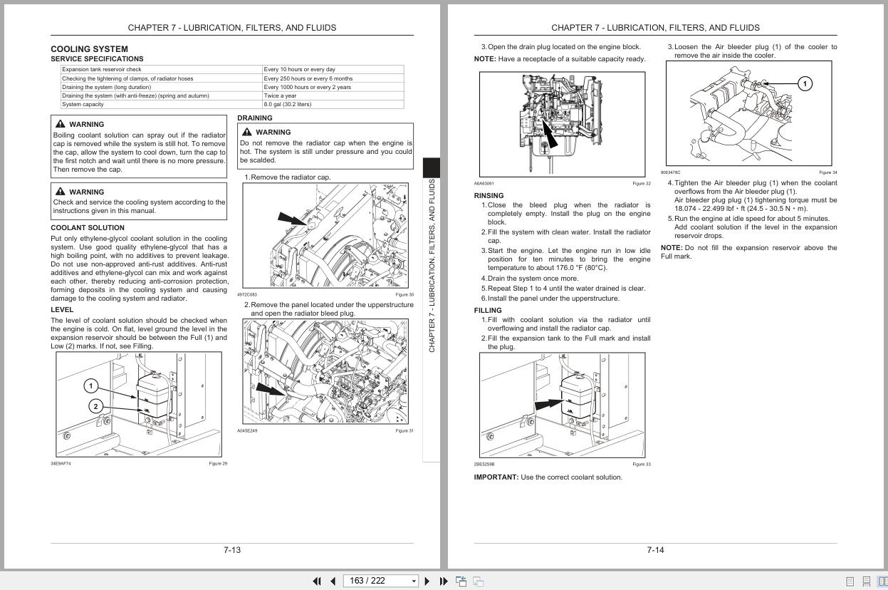
Chapter 7 – Lubrication, Filters, And Fluids
Fluids And Lubricants
Lubrication Chart
Lubrication Points
Fluid Levels
Engine
Cooling System
Fuel System
Releasing Pressure In The Hydraulic System
Hydraulic System
Bleeding Air From The Hydraulic Components
Air Filter
Swing Reduction Gear
Travel Reduction Gears
Chapter 8 – Maintenance And Adjustments
Tracks
Track Rollers And Idler Wheels
Radiator And Oil Cooler
Fan And Alternator Belt
Inspecting And Cleaning The Machine
Checking For Cylinder Leakage
Fire Extinguisher (Not Supplied)
Welding On The Machine
Plastic And Resin Parts
Air Conditioning
Hardware Torque Inspection
Engine Troubleshooting
Chapter 9 – Electrical Systems
Fuses
Battery
Connecting One Or Two Booster Batteries
Alternator
Starter Motor
Replacing A Bulb
Magnet System Maintenance Specification
Chapter 10 – Transportation & Storage Instructions
Transporting The Machine
Lifting The Machine
Machine Storage
Chapter 11 – Specifications
Engine
Electrical Systems
Hydraulic System
Weights
Undercarriage
Capacity Of Systems And Components
Attachment
Electrical Accessories For Magnet
Machine Overall Dimensions
Working Range
Lifting Capacities – Iso Ratings
Remotecare
Provisional
Chapter 12
Index
REALEASE :
REALEASE :

REALEASE :
REALEASE :
REALEASE :
REALEASE :

REALEASE :
21.09.2021
REALEASE :
21.09.2021
REALEASE :
REALEASE :
REALEASE :
REALEASE :
REALEASE :
REALEASE :

REALEASE :
REALEASE :
 Automotive - Heavy Equipment - Truck & Bus - Forklift - Crane