
2 ITEMSVIEW CART


Total: 330.00$

Expert Support
Full Speed
100% Working
30$ USD
List of Files:
02i-Motor 3 Cilindros.Pdf (25 Pages)
Index
Time For Complete Taking Out Placing Back
Cylinder Block, Crankshaft, Pistons And Connecting Rods
Cylinder Head And Rocker Shaft
Timing Case And Camshaft
Fuel Injection Equipment
Sump And Pump Of Lubrificating Oil
Lubrication System
Water Pump
Induction Manifold And Exhaust, Escapment
Fuel System
Ayr System Admission
Cooling System
03i-Motor 4 Cilindros.Pdf (53 Pages)
Index
Time For Complete Taking Out Placing Back
Engine And Acessories
Cylinder Block
Crankshaft, Pistons And Connecting Rods
Cylinder Head And Rocker Shaft
Timing Case And Camshaft
Fuel Injection Equipment
Sump And Dynamic Balancer
Sump And Balancer With Turbo
Lubrication System
Lubrificating Oil Filter And Heating Changer
Water Pump
Induction Manifold And Exhaust, Escapment
Induction Manifold And Exhaust, Escapment With Turbo
Fuel System
Fuel System Saddle Type (Plate)
Fuel System Saddle Type (Plastic)
Fuel Maintenance System (Plastic Tank)
Fuel Maintenance System
Ayr System Admission
Air Cleaner And Pre Filter
Cooling System
Cylinder Head Coupler, Hourmeter Drive
Turbocharged
04i-Motor 6 Cilindros.Pdf (39 Pages)
Index
Time For Complete Taking Out Placing Back
Fixations Engine
Engine And Acessories
Cylinder Block, Crankshaft, Pistons And Conecting Rods
Set Rocker Level And Cylinder Head Cover
Valves Cover Cylinder Head
Timing Gear And Camshaft
Oil Sump And Lubricanting Oil Pump
Lubricanting Oil Filter And Oil Coller
Cooling System
Fan And Extension
Induction Manifold And Exhaust
Exhaust System
Turbocharged Turbo Charged Engine
Fuel Injection Equipment
Low Pressure Fuel System
Fuel Tank
Fuel System Saddle Type (Plastic)
Fuel Maintenance System (Plastic Tank)
05i-Embreagem.Pdf (9 Pages)
Index
Time For Complete Taking Out Placing Back
Single Clutch
Doble Clutch
Slpit Torque Diaphragm Spring Clutch
06i-Eixo Dianteiro 4×2 E 4×4.Pdf (31 Pages)
Index
Time For Complete Taking Out Placing Back
Shaft Fix
Front Axle 2 Wheel Drive
Front Axle 4 Wheel Drive
Front Axle 4 Wd-Carraro
Front Axle – Side Drive Carraro
Front Axle 4 Wd-Zf Middle Drive
Front Axle 4 Wd-Zf Side Drive
Front Axle – Side Drive Zf
07i-Transmission 8 Velocidades.Pdf (13 Pages)
Index
Time For Complete Taking Out Placing Back
Fixation Engine To Transmision, Levers
Kit Transmission
Selectors Shafts And Folks
Shafts And Gears
Epicyclic Unit
08i-Transmission 12 Velocidades.Pdf (17 Pages)
Index
Time For Complete Taking Out Placing Back
Cover And Levers
Constant Mesh Transmission
Shaft And Forks Selectors
Kit Input Shaft
Outlet Whole
Kit Secundary Shaft
Epicyclic Unit
09i-Transmission 12 Velocidades Sincronizadas.Pdf (17 Pages)
Index
Time For Complete Taking Out Placing Back
Cover And Levers
Transmission – Syncro
Shaft And Forks Selectors
Kit Input Shaft
Kit Outlet Shaft
Kit Secundary Shaft
Epicyclic Unit
1-General Information.Pdf (25 Pages)
Index
Introduction
Pre-Delivery, Delivery On The Farm And Warranty
Warranty Procedure
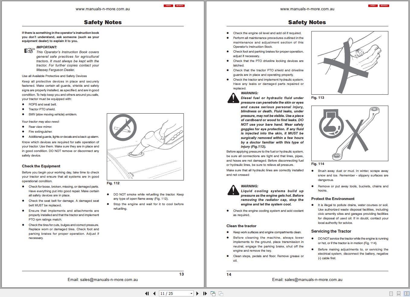
Safety
Safety Alert Symbol And Terms
Tractor And Implement Safety
A Word To The Operator
Danger: Follow A Safety Program
Roll Over Protective Structure (Rops)
Prepare For Safe Operation
Know Your Equipment
Check The Equipment
Protect The Environment
Servicing The Tractor
Starting
Mount And Dismount Safely
Starting Fluid
Work Safety
Follow Safe Operating Practices
General Operating Hazards
Implements And Attachments
Safety – Towing
Road Transport
After Operation
Safety Decal Locations
1-Introduction.Pdf (7 Pages)
Index
Presentation And Utilization
Times
Times Revision
Improvements
Using Special Tools
Example Of R.T.S Analysis
Conclusions
Failure Codes
10i-Transmission 18 Velocidades.Pdf (17 Pages)
Index
Time For Complete Taking Out Placing Back
Levers Cover
Transmission
Shafts And Forks Selectors
Kit Input Shaft
Kit Outlet Shaft
Set Intermediate Shaft
11i-Transmissão Com Reversão Automática.Pdf (17 Pages)
Index
Time For Complete Taking Out Placing Back
Torque Converter
Levers Cover
Transmission
Shafts And Forks Selectors
Kit Input Shaft
Kit Outlet Shaft
Kit Secundary Shaft
12i-Eixo Traseiro.Pdf (35 Pages)
Index
Time For Complete Taking Out Placing Back
Middle Body
Final Drive
Semi-Shaft
Oil – Bath Brake
Middle Body 540 Rpm 2rm
Middle Body Without Pto
Middle Body With Pto 540/1000 Rpm
Pinion And Diferential
Diferential
Rear Axe, Differential Lock
Propeler Shaft, Spacer And Fixture (To 4wd Transmission – Central)
Spacer And Gousing
Propeler Shaft, Housing And Fixture
Lateral Drive Box
13i-Tdp E Tdpi.Pdf (11 Pages)
Index
Time For Complete Taking Out Placing Back
Ipto
Pto Shaft And Intermediate Shaft
Clutch, Cover And Controls
Lever And Guard
14i-Sistema De Direção.Pdf (31 Pages)
Index
Time For Complete Taking Out Placing Back
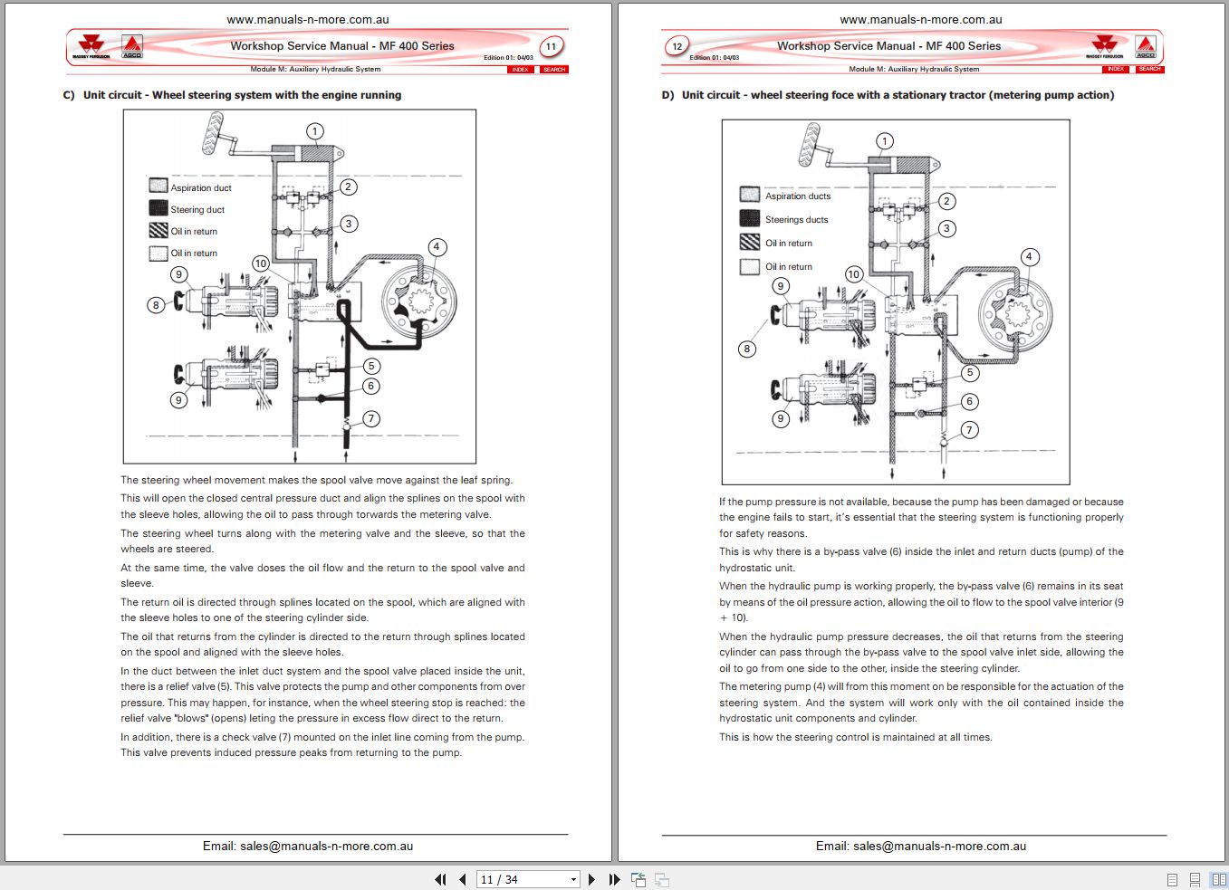
Hidrostatic Direction
Tank, Stering Hidraulic Pump
Hidrostatic Unit And Steering Pump
Remote Control And Steering
Hidrostatic Unit
Hydraulic Cylinder Steering
Remote Control With 1 Boddy
Remote Control With 2 Boddy
Remote Control With Flexible Tubes
15i-Sistema De Levante Hidráulico.Pdf (31 Pages)
Index
Time For Complete Taking Out Placing Back
Traction Bar
Master Beam And Traction Bar
Hydraulic Lift Cover
Hydraulic Lift
Isyp Hydraulic Pump
Auxiliar Cylinder
Lift Arms
Stabiliser
16i-Sistema Elétrico.Pdf (15 Pages)
Index
Time For Complete Taking Out Placing Back
Battery, Support And Rod
Instruments Panel
Front Electric System
Instruments Panel
Headlamp And Rotating Lamp
Horn And Blinker Relay
17i-Lataria.Pdf (45 Pages)
Index
Time For Complete Taking Out Placing Back
Front Mudguard
Rear Mudguard
Front Grille And Grille
Sheet Metal – Hood
Sheet Metal
Accelerator
Seat
Protection Estructure Rigid
Protection System Inclinable
Canopy
Brake Pedals And Clutch
Deflector
Footsteps
Emblems
Velocity Scale
Pane
18i-Rodagem.Pdf (17 Pages)
Index
Time For Complete Taking Out Placing Back
Front Wheels
Front Wheels 4×4
Rear Wheels
Bracket And Front Wheight
Rear Wheel Weights
19i-acessórios.pdf (13 Pages)
Index
TIME FOR COMPLETE TAKING OUT PLACING BACK
RANGE BOX SPEED
STARTING HEATER
LIGHTING BRACKET AND SIGNALIZING
KIT OIL PIPE
GREASE GUN
2-instruments.pdf (16 Pages)
Index
Identification générale des instruments et des commandes
Tableau de bord
Identification générale
Indicateurs
Voyants lumineux
Commandes électriques
Utilisation des commandes
1 – Volant de direction
2 – Levier de commande de l’accélération manuelle
3 – Pédale d’accélération
4 – Pédale d’embrayage
5 – Pédales de freins et verrouillage
6 – Dispositif de verrouillage du frein de stationnement
7 – Levier de marche 4 RM
8 – Levier de commande PDF/IPDF
9 – Levier de contrôle de position du système hydraulique
10 – Levier de contrôle d’effort du système hydraulique
11 – Levier(s) de commande hydraulique auxiliaire
12 – Soupape distributrice du système hydraulique auxiliaire (uniquement MF 415)
13 – Commande de “Réponse” du système hydraulique
14 – Pédale de verrouillage du différentiel
15 – Levier principal de vitesses (tous tracteurs)
16 – Levier sélecteur de régime double: Haut (High) et Bas (Low) (tous tracteurs)
17 – Levier sélecteur de vitesses (Lièvre et Tortue): uniquement les tracteurs avec boîte de vitesses 12×4
18 – Levier de commande de vitesses rampantes (Optionnel sur MF 415 à 440)
Autres instruments
Siège du conducteur et ceinture de sécurité
Ajustement de la ceinture de sécurité
Levier de dételage automatique
Fonction démarrage position neutre
Signalisation Véhicule Lent
Prise électrique de la remorque
Plaque d’immatriculation et feu (Optionnel)
3-operation.pdf (36 Pages)
Index
Starting and Stopping the Engine
Before Starting
Neutral Start Switch Check
Normal Start – Warm Weather
Normal Start – Cold Weather (Thermostart)
Starting the Tractor with Jump Leads
Towing to Start the Engine
Starting Fluid – Emergency use Only
Stopping the Engine – Before working on the engine or tractor
Emergency Stop
Operating the Tractor
Towing
Driving In Deep Water
Having Started the Engine
General Operating Advice
Clutch Pedal Operation Operating the Tractor
Hand and Foot Throttle
Use of differential lock pedal
Brakes correct usage
Making sharp turns
Four-wheel Drive Front Axle (If fitted)
Running-In
Selecting the correct gear
Use of the travel speed chart
Power Take-off (PTO) operation
Changing the clutch stages
Attaching to the PTO
PTO / IPTO output shaft exchange from 540 to 1000 rpm or vice-versa
Hydraulic Lift System
Draft control
Position control
Response control
Transport Position
Constant Pumping – Blue Sector
Lift system adjustments
Attaching an implement
Detaching an implement
Pressure relief valve
Auxiliary hydraulic system
General recommendations
Dependent auxiliary hydraulic system (only MF 415)
Independent, high-flow auxiliary hydraulic system
Valve of variable flow rate
Operating a Front End Loader
Using Implements Requiring Large Volumes of Oil
Transport Chains
Swinging Drawbar
Attaching and detaching trailed equipment
Drawbar height adjustment
Drawbar length adjustment
Drawbar lateral position adjustment
Automatic hitch (Optional accessory)
Roll-over Protective Structure (ROPS) – When equipped with
4-maintenance.pdf (66 Pages)
Index
Maintenance chart
Routine Service
Chart 1: new tractor maintenance
Chart 2: Regular Maintenance
Massey Ferguson Recommended Lubricants
Grease Points
Safety in Servicing
Protect the Environment
Service Access
Engine lubrication
Cleaning of sump breather tube
Valve Tip Clearances (Every 1000 hours – To be carried out at the MF Dealer)
Fuel System
Engine idle checking and adjustment
Removing Water or Impurities (Daily, befor first starting)
Sedimentor and pre-filter
Change of fuel filter element(s)
Removing Air from the Fuel System
Fuel Injectors (Every 1000 Hours or Annually)
Fuel Lift Pump filter cleaning
Dry type Air Cleaner
Oil bath type Air Cleaner
Cooling System
Coolant level
Frost Precautions (Cold Climate)
Radiator
Clutch
Checking and adjustment of the two-stage clutch application
Live PTO Clutch adjustment (Every 1000 hours)
Brakes – pedals free travel adjustment
Differential Lock pedal
Transmission and Hydraulics
Cleaning of breathers
Inspection of gear lever rubber cowls
Oil Level
Draining oil and cleaning hydraulic lift system pump screen filter
Changing transmission/auxiliary hydraulic/steering oil
Rear final reducers
Front axle
Elimination of play in front axle king pins – 2 WD axle
Checking and adjustment of front wheel alignment – 2WD and 4 WD
Checking of fluid level (MF 415 only)
Replacement of filter and steering fluid – Every 500 Hours
Four – Wheel Drive Front axle
Front differential Oil changing (Every 500 Hours)
Track adjustment
2 WD front axle track adjustment
4 WD front axle track adjustment
Rear axle track adjustment
Tires
Check tire pressures every 50 hours or every week whichever is the sooner
Cross-ply Tires
Generic tire inflation table (valid for maximum speed of 32 km/h (20 mph)
Water Ballasting
Water/Calcium Chloride Solution — Capacity and Weight
Wheel Nut Tightness
Compatibility of front and rear tires on 4 WD tractors
Electrical Equipment
Cares to be taken with electrical equipment
Battery
Alternator and Fan Belt
Headlights adjustment
Bulb Replacement
Fuses replacement
Safety Signs
Cleaning the Tractor
Storing the Tractor
Returning to work
5-specifications.pdf (16 Pages)
Index
Engine
Lubrication system
Air cleaning system
Fuel system
Cooling system
Electrical system – powers and capacities
Clutch
Gearbox – types and application
Theoretical road speeds (km/h – engine at full power)
Rear axle
Front axle
Brakes
Power steering
Hydraulic lift system
Auxiliary hydraulic system
Power Take-Off
Weights – kgf
Dimensions – mm
Filling capacities – liters
Wheel nut torques – kgf.m
Drawbar
Tires
General electrical circuit
6-quadroman-s400ing.pdf (1 Pages)
a-introducs400bucing.pdf (44 Pages)
Index
1 – Presentation
1.1 – How to use this Manual
1.2 – Recording changes and updates made to this Manual
2 – Safety
3 – Correct workshop techniques
4 – Basics of measurement
4.1 – Examples of instruments used in measurement
4.2 – Examples of measurement
4.3 – General concepts
5 – General table of recommended torques for bolts
6 – Technical units
6.1 – Conversion table
6.2 – Equivalence between units – Imperial and SI systems
6.3 – Prefixes of technical units
7 – Loctite products for the workshop
8 – AGCO environmental policy
9 – Compulsory recycling of batteries
ajuda 400 buc_ingl.pdf (3 Pages)
Index
Page 1
Page 2
Page 3
b-aberturas400bucing.pdf (21 Pages)
Index
1 – Introduction
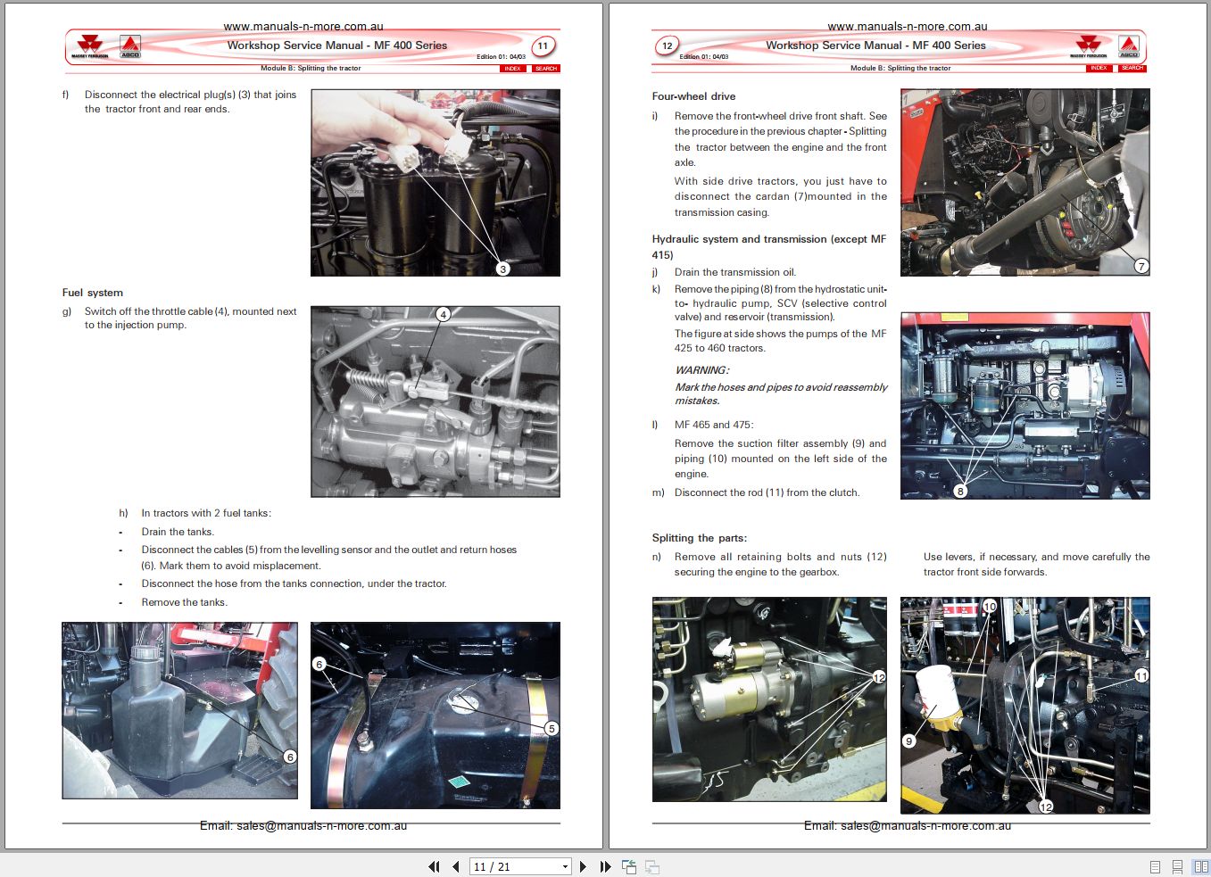
2 – Splitting the tractor between the engine and the front axle
2.1 – Tractor reassembling between the engine and the front axle
3 – Splitting the tractor between the engine and the gearbox
3.1 – Reassembling between the engine and gearbox
4 – Splitting the tractor between the gearbox and the rear axle
4.1 – Tractor reassembling between the gearbox and the rear axle
5 – ROPS + canopy + fender assy removal
6 – Front hood sheet metal removal
c-eixo4x2-s400bucing.pdf (12 Pages)
Index
1 – Introduction
2 – Wheel alignment
2.1 – Camber
2.2 – Sleeve inclination
2.3 – Caster
2.4 – Toe-in
3 – Front wheel hubs
3.1 – Wheel hub disassembly
3.2 – Components inspection
3.3 – Assembly and adjustment of the hubs pre-load
4 – Outer arm and spindle shaft
4.1 – Adjustment of the spindle shaft gap
4.2 – Bushings of the shaft bushing (replacement)
5 – Front axle central beam
5.1 – Radial and axial gap checking for the central beam
5.2 – Replacement of the steering system bushings (Except MF 415)
6 – MF 415 tractor axle
d1-carraros400bucing.pdf (35 Pages)
Index
1 – Introduction
1.1 – Carraro axles for the 400 Series
1.2 – Basic technical specifications
2 – Final drive
2.1 – Components identification
2.2 – Final drive disassembly
2.3 – Final drive reassembly and adjustments
3 – Final drive pivoting
3.1 – Disassembly
3.2 – Reassembly
4 – Half-shaft spiders
4.1 – Disassembly
4.2 – Reassembly
5 – Bushingings and retainers of trumpets and pivots
5.1 – Removal of bushings and retainers
5.2 – Components inspection
5.3 – Assembly of bushings and retainers
6 – Pinion and differential assy
6.1 – Components Identification
6.2 – Front axle removal
6.3 – Removal and disassembly of differential
6.4 – Pinion disassembly
6.5 – Components inspection of differential and pinion
6.6 – Pinion reassembly and adjustments
6.7 – Differential reassembly
6.8 – Final adjustments of the pinion and differential assy
7 – Driving box and front bearing shell
7.1 – Components identification
7.2 – Driving box disassembly
7.3 – Components inspection
7.4 – Reassembly and adjustment of driving box
7.5 – Bearing removal from front bearing shell and step-up gearbox
8 – Steering cylinder
8.1- Components Identification
8.2 – Disassembly of steering cylinder
8.3 – Components inspection
8.4 – Reassembly of steering cylinder
9 – Tightening torques
d2-zf-apls400bucing.pdf (59 Pages)
Index
1 – Introduction
1.1 – ZF axles for the 400 Series tractors
1.2 – Basic technical specifications
2 – Final drives
2.1 – Identification of components
2.2 – Final drive disassembly
2.3 – Half-shaft spiders
2.4 – Inspection of components
2.5 – Reassembly and adjustments
3 – Differential, pinion and trumpets
3.1 – Identification of components
3.2 – Front axle removal
3.3 – Differential removal and disassembly
3.4 – Differential components inspection
3.5 – Differential reassembly and adjustments
3.6 – Pinion disassembly and inspection
3.7 – Adjustment of the differential pre-load – all axles
3.8 – Pinion positioning
3.9 – Pinion pre-load adjustment
3.10 – Adjustment of gap between crown teeth and pinion – all axles
3.11 – Checking of the mating area between crown teeth and pinion
4 – Secondary drive box, brackets and bearings
4.1 – Identification of components
4.2 – Disassembly of brackets and bearings
4.3 – Assembly and adjustment of brackets and bearings
4.4 – Disassembly of the secondary drive box
4.5 – Assembly and adjustment of the secondary drive box
5 – Mechanical-type side drive box
5.1 – Operation
5.2 – Identification of components
5.3 – Disassembly of the drive box
5.4 – Reassembly of the side drive box
6 – Spacer and four-wheel central drive box
6.1 – Identification of drive box components
6.2 – Drive box servicing
6.3 – Transfer box (spacer) components identification
6.4 – Transfer box servicing
7 – Steering hydraulic cylinder
7.1 – Identification of components
7.2 – Removal and disassembly
7.3 – Inspection of components
7.4 – Reassembly and adjustments
8 – Adjustment specifications
8.1 – APL 335
8.2 – APL 345/350
e-perkinss400bucing.pdf (29 Pages)
Index
1 – Adjustment of valve tip clearance
2 – Nozzles inspection
2.1 – Atomization and pressure test
2.2 – Sealing test
2.3 – Atomization and noise test
3 – Adjustment of the injection point
4 – Compression test for cylinders
5 – Basic technical specifications
5.1 – A 3.152 Engine
5.2 – A 4.236 Engine
5.3 – P 4000 engines
5.4 – 1000 Series engines
6 – Workshop specifications
6.1 – Cylinder head assembly
6.2 – Cylinders block assembly
6.3 – Distribution box (Includes all gears)
6.4 – Pistons. rings and connecting rods
6.5 – Crankshaft assembly
6.6 – Oil sump and lubrication system
6.7 – Cooling system
6.8 – Fuel system
6.9 – Turbocharger
6.10 – Recommended tightening torques (Values in N.m)
f-embreagems400bucing.pdf (35 Pages)
Index
1 – Types of clutches used on MF 400 Series tractors
2 – Clutches and flywheels fitted on the MF 400 Series tractors
3 – General information and recommendations about clutches
3.1 – The most frequent causes of clutch overheating
3.2 – Hints to avoid damages to the clutch and inconveniences during clutch removal and refitment
4 – Dual-stage and split-torque clutch: components identification
5 – Clutch removal and disassembly
5.1 – Dual-stage and split-torque clutch disassembly
6 – Inspection and refitment of the components
6.1 – Main pressure plate machining – or plateau
6.2 – False flywheel (9) machining
6.3 – HD split-torque clutch
6.4 – HD single clutch with cerametallic disc Z
7 – Clutch reassembly (dual-stage and split-torque)
8 – Engine flywheel
8.1 – Flywheel machining
8.2 – Flywheel ring gear (crown)
8.3 – Flywheel refitment
8.4 – Flywheel alignment
9 – Clutch refitment and final adjustments
9.1 – Clutch refitment to the flywheel
9.2 – Release levers adjustment
9.3 – Pedal height adjustment
9.4 – Checking and adjustment of the clutches 2nd stage application
10 – Clutch troubleshooting
g1-8x2vsliding-s400bucing.pdf (32 Pages)
Index
1 – Introduction
1.1 – Identification of the gearbox components
1.2 – Power flows of the 8×2 speed transmissions
2 – Lever cover and gear shift levers
2.1 – Components identification
2.2 – Disassembly and inspection
2.3 – Reassembly
3 – Shafts, selector rails and forks
3.1 – Components identification
3.2 – Disassembly and inspection
3.3 – Reassembly
4 – Slow/Fast ranges assy
4.1 – Components identification
4.2 – Removal and disassembly
4.3 – Reassembly
5 – Clutch release mechanism
5.1 – Components identification
5.2 – Disassembly and inspection
5.3 – Assembly
6 – Brake pedal cross-shaft
6.1 – Components identification
6.2 – Disassembly and inspection
6.3 – Reassembly
7 – Gearbox inner assy disassembly and inspection
7.1 – Input shaft(s) and front flange
7.2 – Disassembly and inspection
7.3 – PTO output shaft
7.4 – Main shaft
7.5 – Layshaft (lower)
7.6 – Reverse gear assy
8 – Gearbox inner assy reassembly
8.1 – Reverse gear assy
8.2 – Layshaft (lower)
8.3 – Main shaft
8.4 – Transmission input shaft , PTO output shaft and the input housing assy
9 – Creeper
g3-eatoncm-s400bucing.pdf (47 Pages)
Index
1 – Introduction
1.1 – Gearbox components general identification
1.2 – Eaton 12×4 gearbox power flows
1.3 – Diagram of gears
2 – Gearbox removal and adaptation to service support
3 – Speed selector system – foot step type tractors
3.1 – Gear shift levers and cover
3.2 – Shafts and forks
4 – Gear selector system – cab tractors
4.1 – Side-shift system
4.2 – Gear levers
4.3 – Shift lever shafts and forks
5 – Clutch mechanisms
5.1 – Components identification
5.2 – Disassembly and removal
5.3 – Reassembly
6 – Slow and Fast speed range assy
6.1 – Components identification
6.2 – Removal and disassembly
6.3 – Reassembly
7 – Front retainer flange and input shafts
7.1 – Components identification
7.2 – Removal and disassembly
7.3 – Flange assy reassembly
7.4 – Adjustment of the axial clearance of the High & Low ranges upper assy
8 – Main shaft (or output shaft)
8.1 – Components identification
8.2 – Main shaft removal and disassembly
8.3 – Reassembly and adjustment of the main shaft assy
9 – PTO output shaft and layshaft (lower shaft)
9.1 – Components identification
9.2 – PTO output shaft removal and disassembly
9.3 – Layshaft removal
9.4 – Layshaft (lower) assy reassembly
9.5 – Adjustment of the axial clearance of the High and Low ranges lower assy
9.6 – PTO output shaft reassembly
10 – Reverse gear assy
10.1 – Components identification
10.2 – Reverse gear assy removal and disassembly
10.3 – Reverse gear assy reassembly
11 – Components inspection and failure diagnosis
11.1 – Recommendations on bushings and sleeves
11.2 – Coupling sets
12 – Creeper
Creeper maintenance
g4-eatonsn-s400bucing.pdf (37 Pages)
Index
1 – Introduction
1.1 – Shifter components general identification
1.2 – Eaton 12×4 gearbox power flows
1.3 – Diagram of gears
2 – Gearbox removal and adaptation to service support
3 – Clutch mechanism
3.1 – Components identification
3.2 – Disassembly and removal
3.3 – Reassembly
4 – Gear selector system: shift lever shafts and forks
4.1 – Foot step type tractors (levers mounted on the gearbox)
4.2 – Cab tractors (side levers)
5 – Fast & Slow assembly
5.1 – Components identification
5.2 – Removal and disassembly
5.3 – Reassembly
6 – Front flange and input shafts
6.1 – Components identification
6.2 – Removal and disassembly
6.3 – Flange assy reassembly
6.4 – Axial clearance adjustment of the High & Low ranges upper assy
7 – Main shaft (or output shaft)
7.1 – Components identification
7.2 – Main shaft removal and disassembly
7.3 – Main shaft assy reassembly and adjustment
8 – PTO output shaft and layshaft (lower)
8.1 – Components identification
8.2 – PTO output shaft removal and disassembly
8.3 – Layshaft removal
8.4 – Layshaft (lower) assy reassembly
8.5 – Axial clearance adjustment of the High/Low ranges lower assy
8.6 – PTO output shaft reassembly
9 – Reverse gear assy
9.1 – Components identification
9.2 – Reverse gear assy removal and disassembly
9.3 – Reverse gear assy reassembly
10 – Synchromesh sets
10.1 -Components identification
10.2 – Reassembly
10.3 – Forks centralization in relation to the coupling rings and hubs
11 – Components inspection and failure diagnosis
11.1 – Recomendations about bushings and sleeves
h-eixotras-s400bucing.pdf (44 Pages)
Index
1 – Description and operation
2 – Final drives
2.1 – Identification of final drive components
2.2 – Final drive removal procedures
2.3 – Final drive disassembly
2.4 – Analysis and/or replacement of components
2.5 – Mounting of final drives
2.6 – Final drive preload adjustment
3 – Trumpets
3.1 – Removal
3.2 – Trumpet reinstallation
4 – Brakes
4.1 – Inspection and adjustment of free pedal travel
4.2 – Brake discs
4.3 – Replacement of protective coifs of expansion plate driving rods
4.4 – Mounting
5 – Differential
5.1 – Differential lock
5.2 – Satellite box and ring gear
6 – Pinion
6.1 – Identification of components
6.2 – Pinion removal – all models
6.3 – Disassembly of the pinion assembly – all models
6.4 – Analysis of components
6.5 – Mounting of the pinion assembly
6.6 – Preload adjustment of pinion bearings
7 – Adjustments and reinstallation of the ring gear and pinion assembly
7.1 – Principles of ring gear and pinion adjustment dynamics
7.2 – Differential preload
7.3 – Adjustment of pinion and ring gear backlash
7.4 – Inspection and adjustment of tooth contact patterns
8 – Half shaft without final drive – MF 415 tractors
8.1 – Identification of components
8.2 – Half shaft disassembly
8.3 – Analysis of components
8.4 – Mounting and adjustment of play at half shaft ends
9 – General technical specifications
i-fergusons400bucing.pdf (36 Pages)
Index
1 – Introduction
1.1 – Hydraulic system components identification
2 – Ferguson hydraulic system operation
2.1 – Hydraulic pump check valve main positionings
2.2 – Depth (Draft) control system
2.3 – Position control system
2.4 – System hydraulic flow diagram
3 – Ferguson hydraulic pump
3.1 – Pump removal, disassembly and inspection
3.2 – Components inspection
3.3 – Griding of the hydraulic pump valve seats – milling tool kit usage FT5004
3.4 – Pump reassembly
3.5 – Refitment and adjustment
4 – Hydraulic lift cover
4.1 – Hydraulic lift cover removal
4.2 – Hydraulic lift cover disassembly
4.3 – Hydraulic lift cover components inspection
4.4 – Hydraulic lift cover assembly
4.5 – Hydraulic lift cover internal adjustments
4.6 – Hydraulic lift cover refitment
4.7 – Hydraulic lift cover adjustments
5 – Outer hydraulic cylinders – MF 460 to 475
5.1 – Components identification
5.2 – Outer cylinder assembly
5.3 – Components inspection
5.4 – Reassembly
6 – System final assembly
l-eletric-s400bucing.pdf (37 Pages)
Index
1 – Presentation
1.1 – Electrical system general specifications
1.2 – Electrical circuit – foot step type tractors
1.3 – Electrical circuit – cab version tractors
2 – Electrical board: fuses, relays, and diodes
2.1 – Foot step version tractors
2.2 – MF 400 tractors with cab
3 – Prestolite Alternator
3.1 – Alternator disassembly
3.2 – Alternator reassembly
3.3 – Alternator testing
4 – Prestolite starter motor
4.1 – Starter motor disassembly
4.2 – Parts cleaning and inspection
4.3 – Reassembly
4.4 – Starter motor testing
5 – Instrument panel
6 – Miscellaneous components
6.1 – Relays
6.2 – Fuel level sender
6.3 – Engine temperature sensor
6.4 – Fuel injection pump solenoid
6.5 – Battery(ies)
m-hidraux-s400bucing.pdf (34 Pages)
Index
1 – Introduction
1.1 – Foreword
1.2 – Hydraulic diagrams
2 – Hydraulic testing
2.1 – Hydrostatic steering system pressure test
2.2 – Pressure test for the auxiliary hydraulic control valves
3 – Danfoss hydrostatic unit
3.1 – Operation – oil flow inside the valve
3.2 – Danfoss unit circuits
3.3 – General identification of components
3.4 – Unit hydraulic connections – identification
3.5 – Special recommedations for overhaul
3.6 – Disassembly and inspection
3.7 – Unit reassembly
4 – Danfoss prioritary valve – tractors MF 465 and 475
5 – Auxiliary hydraulic control valve
5.1 – General identification
5.2 – Control valve hydraulic circuit
6 – Hydraulic pump(s)
6.1 – Identification of components
6.2 – Removal and disassembly
6.3 – Components inspection and troubleshooting
6.4 – Hydraulic pump reassembly
7 – Oil filtering
8 – Heat exchanger (MF 465 and 475)

REALEASE :
03.07.2020
REALEASE :
03.07.2020

REALEASE :
02.06.2020
REALEASE :
02.06.2020

REALEASE :
16.07.200
REALEASE :
16.07.200

REALEASE :
12.06.2020
REALEASE :
12.06.2020

REALEASE :
26.04.2020
REALEASE :
26.04.2020

REALEASE :
03.07.2020
REALEASE :
03.07.2020

REALEASE :
11.06.2020
REALEASE :
11.06.2020

REALEASE :
REALEASE :
 Automotive - Heavy Equipment - Truck & Bus - Forklift - Crane