
1 ITEMVIEW CART

Total: 15.00
Expert Support
Full Speed
100% Working
10 USD
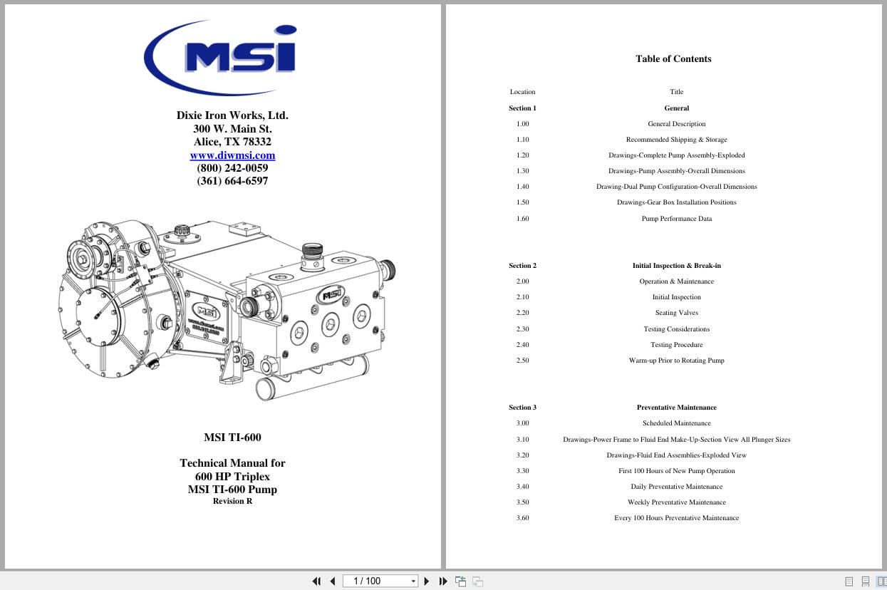
Contents:
Title
General
General Description
Recommended Shipping & Storage
Drawings-Complete Pump Assembly-Exploded
Drawings-Pump Assembly-Overall Dimensions
Drawing-Dual Pump Configuration-Overall Dimensions
Drawings-Gear Box Installation Positions
Pump Performance Data
Initial Inspection & Break-in
Operation & Maintenance
Initial Inspection
Seating Valves
Testing Considerations
Testing Procedure
Warm-up Prior to Rotating Pump
Preventative Maintenance
Scheduled Maintenance
ings-Power Frame to Fluid End Make-Up-Section View All Plunger Sizes
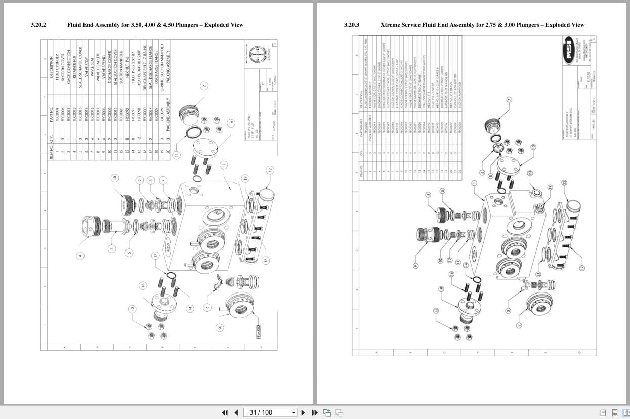
Drawings-Fluid End Assemblies-Exploded View
First 100 Hours of New Pump Operation
Daily Preventative Maintenance
Weekly Preventative Maintenance
Every 100 Hours Preventative Maintenance
Every 250 Hours Preventative Maintenance
Yearly or as Required Preventative Maintenance
Inspection of Bearings & Gears
Lubrication System
Drawing Schematic on Lube System
Drawing- Power Frame Lube Lines-Dual Lube Pipe
Drawing- Gear Reducer Lube Lines
Recommended Lubrication Specifications
General Service Lube Oils for Power Frame
Cold Temperature Service Lube Oils for Power Frame
High Temperature Service Lube Oils for Power Frame
Lubrication Supply System
Lube Pump
Oil Reservoir
Lube System Suction Piping
Lube System Pressure Lines and Oil Filter
Lube System Relief Valve and Relief Return Line
Lube Drain Lines from Plunger Pump to Reservoir
Optional Lube System Equipment
Recommended Plunger Lubrication Specifications
Power End
Power Frame Repair Procedures
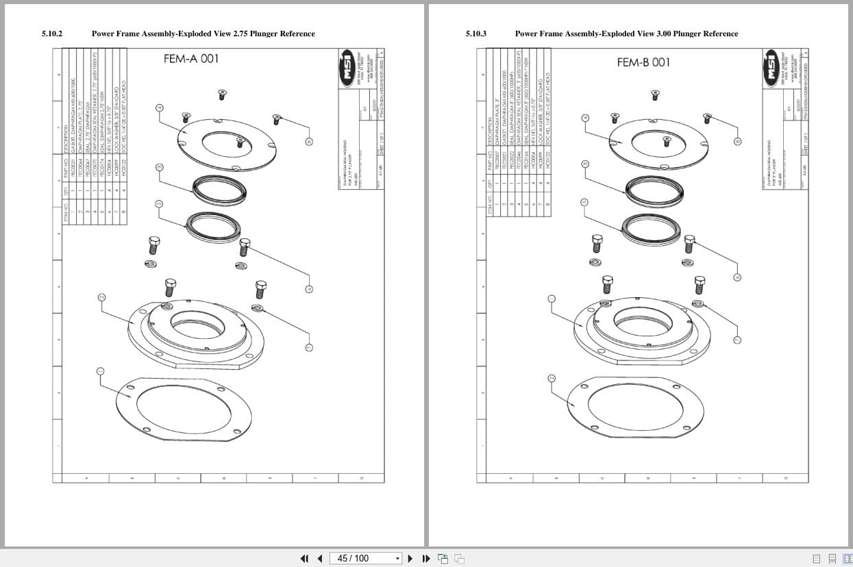
Drawings-Power Frame Assembly-Exploded View and Reference Drawings
Drawing-Power Frame Assembly-Section View
Removing the Crankshaft, Connecting Rods, & Crossheads
Drawing-Connecting Rod Assembly-Exploded
Drawing-Crosshead Assembly-Exploded
Drawing-Diaphragm Seal Housing-Exploded
Drawing- Power Frame Lube Lines-Dual Lube Pipe
Drawing- Power Frame Crank Rotation
Fluid End Repair Procedures
Fluid End Repair Procedures
Drawings-Fluid End Assemblies-Exploded
Drawings-Packing Assembly-Exploded & Section Views for all Plunger Sizes
Removing the Plungers & Packing
Packing Tool Remover in Fluid End
Removing the Valves and Seats
Removing the Discharge Flanges
Removing the Suction Manifold
Removing the Fluid End
Gear Box Repair Procedures
Gear Box Repair Procedures
Removing & Disassembling the Gear Box
Drawing Gear Box-Lube Lines
Drawings-Gear Box-Exploded View
Supercharging
Supercharging the Pump Intake Suction Manifold
Supercharging Operational Parameters
Supercharge Pressure Gauge
Centrifugal Supercharge Pump/Mixing Pump
Primary Suction Piping & Hoses
Secondary Suction Piping & Hoses
Suction Pulsation Dampener
Appendix
Useful Formulas
Conversion Factors
Recommended Torque
Revision History

REALEASE :
REALEASE :
REALEASE :
REALEASE :
REALEASE :
REALEASE :
REALEASE :
REALEASE :
REALEASE :
REALEASE :
REALEASE :
26.06.2019
REALEASE :
26.06.2019

REALEASE :
25.05.2019
REALEASE :
25.05.2019
REALEASE :
REALEASE :
 Automotive - Heavy Equipment - Truck & Bus - Forklift - Crane