
1 ITEMVIEW CART

Total: 100.00

Expert Support
Full Speed
100% Working
30 USD
Contents:
Safety Instructions
1 Basic Safety Information
2 Warning And Instruction Plates
3 Operation
4 Inspection And Maintenance
5 Protecting Electronic Units When Welding
6 Vacuum Pump
Specifications
1 Dimensions
2 Engine
3 Torque Converter
4 Transmission
5 Tyre
6 Rear Axle
7 Front Axle
8 All-Wheel Drive
9 Hydraulic System
10 Brake
11 Steering
12 Equipment
13 Cab
14 Electrical System
15 Operating Fluids And Lubricants
Engine
1 General Information
2 Engine Removal And Installation
Transmission
1 General Description
2 Version
3 Zf Diagnostic System
4 Preface
5 General
6 Tools
7 Disassembly Of Electro-Hydraulic Control Unit And Zf Fine Filter (Expendable Filter)
8 Removal Of Inductive Sensor, Hall Sensor, Breather, Oil Fill And Drain Screw
9 Disassembly Of Engine Connection, Pressure Oil Pump, Converter Counter-Pressure Valve And Temperature Sensor (Measuring Point ‘63’ Downstream Of Converter)
10 Disassembly Of Emergency Steering Pump
11 Disassembly Of Output Shafts
12 Disassembly Of Power Take-Offs
13 Removal Of Drive Shaft, Output Shaft And Couplings
14 Disassembly Of Couplings Kv/Kr/K1/K2/K3/K4, Drive Shaft And Output Shaft
15 Assembly Of Couplings Kv/Kr/K1/K2/K3/K4, Drive Shaft And Output Shaft
16 Installation Of Drive Shaft, Output Shaft And Couplings
17 Assembly Of Power Take-Offs
18 Assembly Of Output Shafts
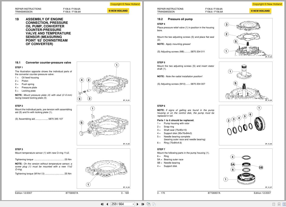
19 Assembly Of Engine Connection, Pressure Oil Pump, Converter Counter-Pressure Valve And Temperature Sensor (Measuring Point ‘63’ Downstream Of Converter)
20 Assembly Of Emergency Steering Pump
21 Assembly Of Inductive Sensor, Hall Sensor, Breather, Oil Fill And Drain Screw
22 Assembly Of Electro-Hydraulic Control Unit With Proportional Valves
23 Function Description And Maintenance Instructions For Spring-Loaded Calliper Fsg 90
Rear Axle
1 General Information
2 General Properties
3 Tandem Axle Removal And Installation
4 Disassembly/Assembly Procedures
Front Axle
1 General Information
2 General Properties
3 All-Wheel Drive (F1066a / F1566a)
4 Front Axle Removal And Installation
5 Disassembly/Assembly Procedures
6 Setting And Testing The Front-Wheel Drive On F1066a And F1566a
Equipment
1 Centre Equipment
2 Front Equipment (Optional), Scraper Blade Or Scarifier
3 Rear Equipment (Optional – Scarifier)
4 Front Frame
Hydraulic System
1 General
2 Wiring Diagrams For Hydraulic System
3 Main Functions
4 Main Components
Brake System
1 Description Of Brake System
2 Brake System Components – Function Description
3 Troubleshooting
Steering System
1 System Description
2 Steering System Components – Function Description
Electrical System
1 Controls And Indicators
2 Circuit Diagram Sheets
3 Wiring Harnesses
4 Error Codes
Cab And Operating Platform
1 Removal And Installation Of Cab And Operating Platform
2 Cab Components
3 Heating And Ventilation

REALEASE :
04.05.2020
REALEASE :
04.05.2020
REALEASE :
13.04.2022

REALEASE :
17.11.2020
REALEASE :
17.11.2020

REALEASE :
08.06.2019
REALEASE :
08.06.2019
REALEASE :
13.04.2022

REALEASE :
08.06.2019
REALEASE :
08.06.2019

REALEASE :
08.06.2019
REALEASE :
08.06.2019

REALEASE :
08.06.2019
REALEASE :
08.06.2019
Automotive - Heavy Equipment - Truck & Bus - Forklift - Crane
