
1 ITEMVIEW CART

Total: 20.00

Expert Support
Full Speed
100% Working
100 USD
List of Files:
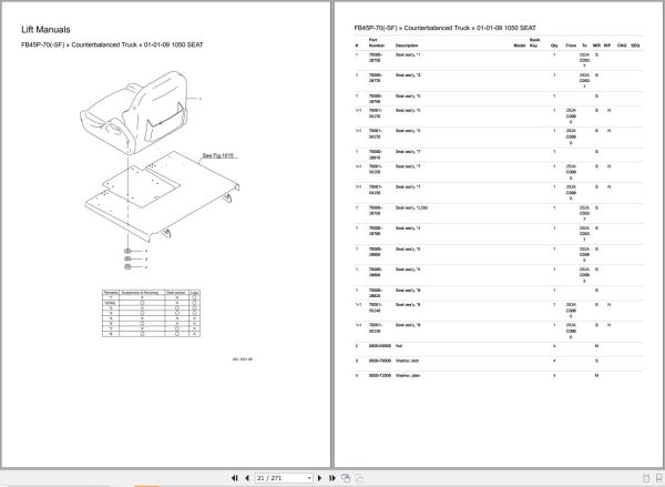
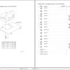
Nichiyu Forklift FB45P-70 FB45P-70SF Parts Catalog.pdf (271 Pages)
Nichiyu Forklift FB35P-70 FB40P-70 FB45PN-70 Operation Manual.pdf (120 Pages):
1. Safe Operation
2. Part Name And Function
3. Driving And Operation
4. Battery And Charger
5. Inspection Prior To Operation
6. Inspection After Operation
7. Periodic Servicing
8. Quick Fault Finding
9. Periodical Replacing Parts
10. Stability Of Forklift Truck
11. Specifications
12. Cold Storage Type Forklift Truck (Option)
13. Sideshift Attachment (Option)
Nichiyu Forklift FB35P-70 FB40P-70 FB45PN-70 Troubleshooting Manual 07W-2202-R1.pdf (108 Pages):
1. Adjustment of SICOS-AC
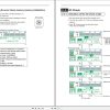
1-1. Explanation of the monitor display
1-2. Explanation of the control board
1-3. SICOS-AC check and adjustment2. Troubleshooting
2-1. Self diagnosis function
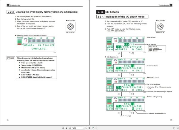
2-2. Error history memory
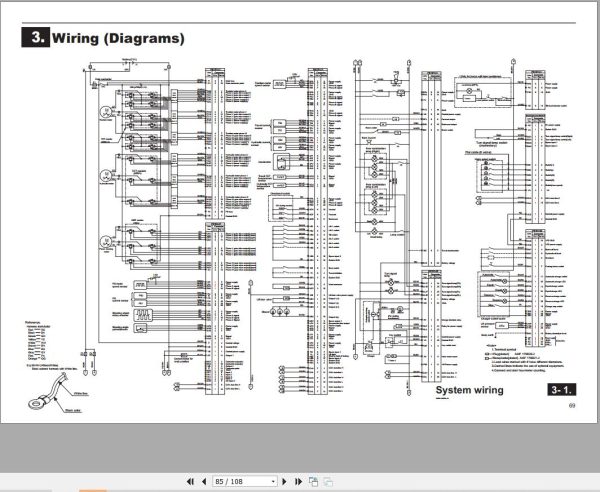
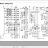
2-3. I/O check3. Wiring (Diagrams)
3-1. System wiring
3-2. Body wiring
3-3. Body harness
3-4. Controller wiring
3-5. Controller harness
3-6. Main Controller ASS’Y
3-7. BC wiring
3-8. Charger harness
3-9. Wiring, revolving light
3-10. Automated fork horizontal stop System wiring
3-11. Automated fork horizontal stop Body wiring
3-12. Wiring, lamp
3-13. Wiring, rear lamp
3-14. Wiring, speed limit4. Reference
4-1.MPU board connectors
4-2.Water resistant connector
Nichiyu Forklift FB35P-70 FB40P-70 FB45PN-70 Workshop Manual 07W-2201-R1.pdf (186 Pages):
1. GENERAL
1-1.Appearance
1-2.Specifications2. FRONT AXLE (DRIVE)
2-1.Location and name
2-2.Disassembly and reassembly
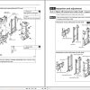
2-3.Inspection and adjustment
2-4.Troubleshooting3. REAR AXLE (STEERING)
3-1.Disassembly and reassembly
3-2.Inspection and adjustment
3-3.Troubleshooting4. TYRE
4-1.Name and tyre size
4-2.Inspection and adjustment
4-3.Troubleshooting5. STEERING
5-1.Location and name
5-2.Disassembly and reassembly
5-3.Inspection and adjustment6. BRAKE
6-1.Location and name
6-2.Disassembly and reassembly
6-3.Inspection and adjustment
6-4.Troubleshooting7. HYDRAULIC SYSTEM
7-1.Oil piping circuit7a. HYDRAULIC PUMP
7a-1. Location and name
7a-2. Disassembly and reassembly
7a-3. Inspection and adjustment
7a-4. Hydraulic pump – troubleshooting7b. OIL TANK AND OIL PIPING
7b-1. Location and name
7b-2. Disassembly and reassembly
7b-3. Inspection and adjustment
7b-4. Troubleshooting7c. CONROL VALVE
7c-1. Location and name
7c-2. Disassembly and reassembly
7c-3. Inspection and adjustment
7c-4. Troubleshooting7d. POWER STEERING PUMP AND PIPING
7d-1. Location and name
7d-2. Disassembly and reassembly
7d-3. Inspection and adjustment7e. CYLINDER
7e-1. Location and name
7e-2. Disassembly and reassembly
7e-3. Inspection and adjustment
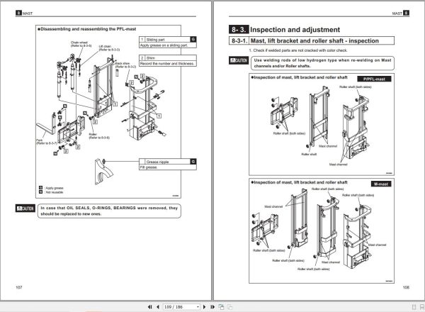
7e-4. Troubleshooting8. MAST
8-1. Location and name
8-2.Disassembly and reassembly
8-3.Inspection and adjustment
8-4.Troubleshooting9. MOTOR
9-1. Location and name
9-2. Disassembly and reassembly
9-3. Inspection and adjustment
9-4. Troubleshooting10. ELECTRIC PARTS
10-1. Location and name10a CONTROL UNIT
10a-1. Location and name
10a-2. Disassembly and reassembly
10a-3. Check and replacement10b. DISPLAY PANEL AND DIRECTIONAL SWITCH
10b-1. Disassembly and reassembly10c. ACCELERATOR
10c-1. Disassembly and reassembly10d. CHARGER (BUILIT – IN)
10d-1. Disassembly and reassembly
10d-2. Inspection and replacement
10d-3. Inspection After Assembly
10d-4. Charging procedure
10d-5. Voltage tap10e. BATTERY
10e-1. Disassembly and reassembly
10e-2. Inspection and adjustment11. LASER POINTER (OPTION)
11-1. Adjustment12. SERVICE DATA
12-1. Standard work hours
REALEASE :
REALEASE :
REALEASE :
REALEASE :

REALEASE :
22.02.2021
REALEASE :
22.02.2021

REALEASE :
21.02.2020
REALEASE :
21.02.2020

REALEASE :
REALEASE :
REALEASE :
REALEASE :
REALEASE :
REALEASE :
REALEASE :
REALEASE :
Automotive - Heavy Equipment - Truck & Bus - Forklift - Crane