
10 ITEMSVIEW CART


Total: 765.00

Expert Support
Full Speed
100% Working
40 USD
List of Files:
01_DIAGRAM LIFTING POINTS HR10 & 12 D80461 (issue 004) 36978.pdf (2 Pages)
02_HOSE DIAGRAM HR12 ECO SOM D80525 (issue 005) 36978.pdf (1 Pages)
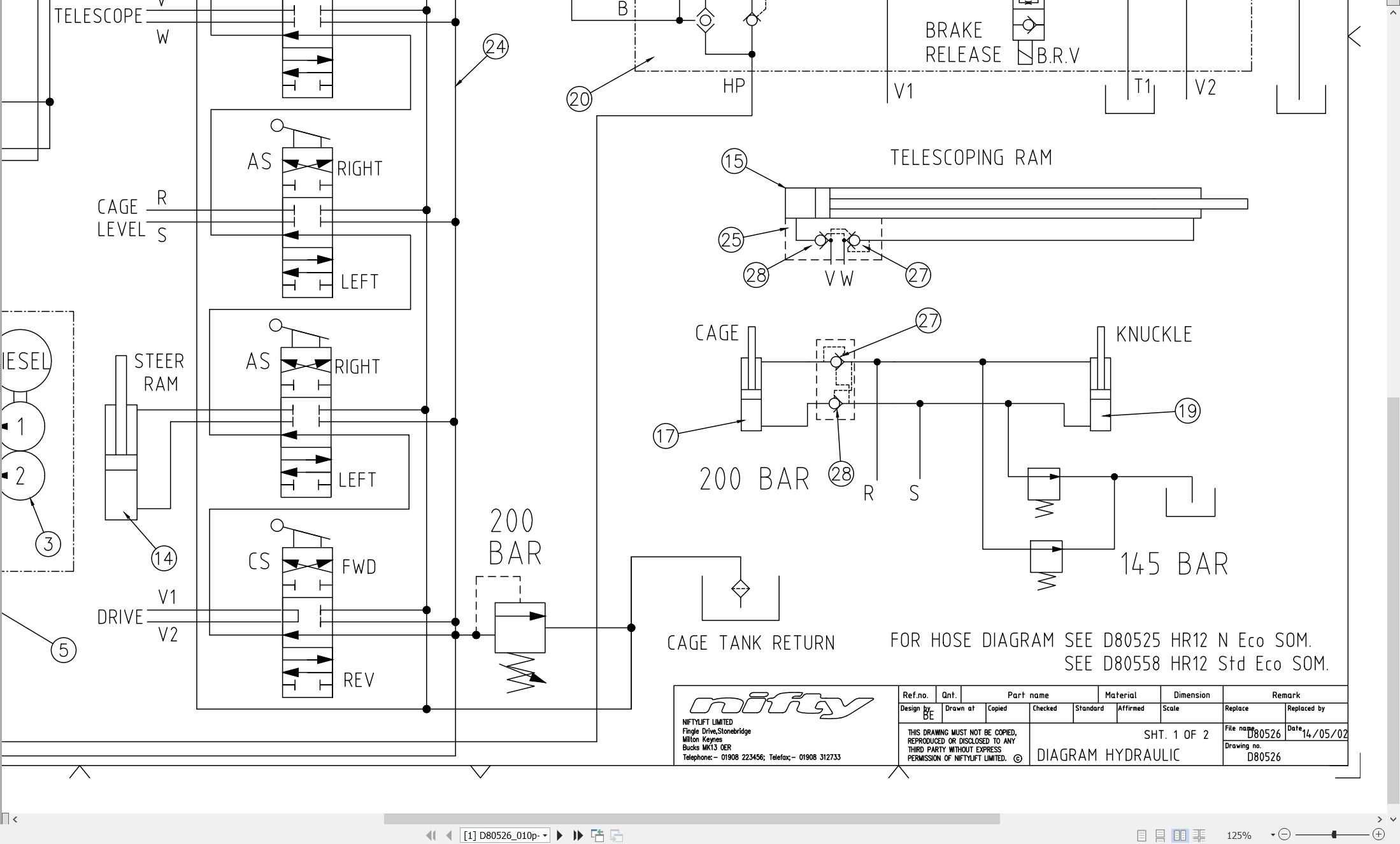
03_HYDRAULIC DRG HR12 D80526 (issue 010) 36978.pdf (2 Pages)
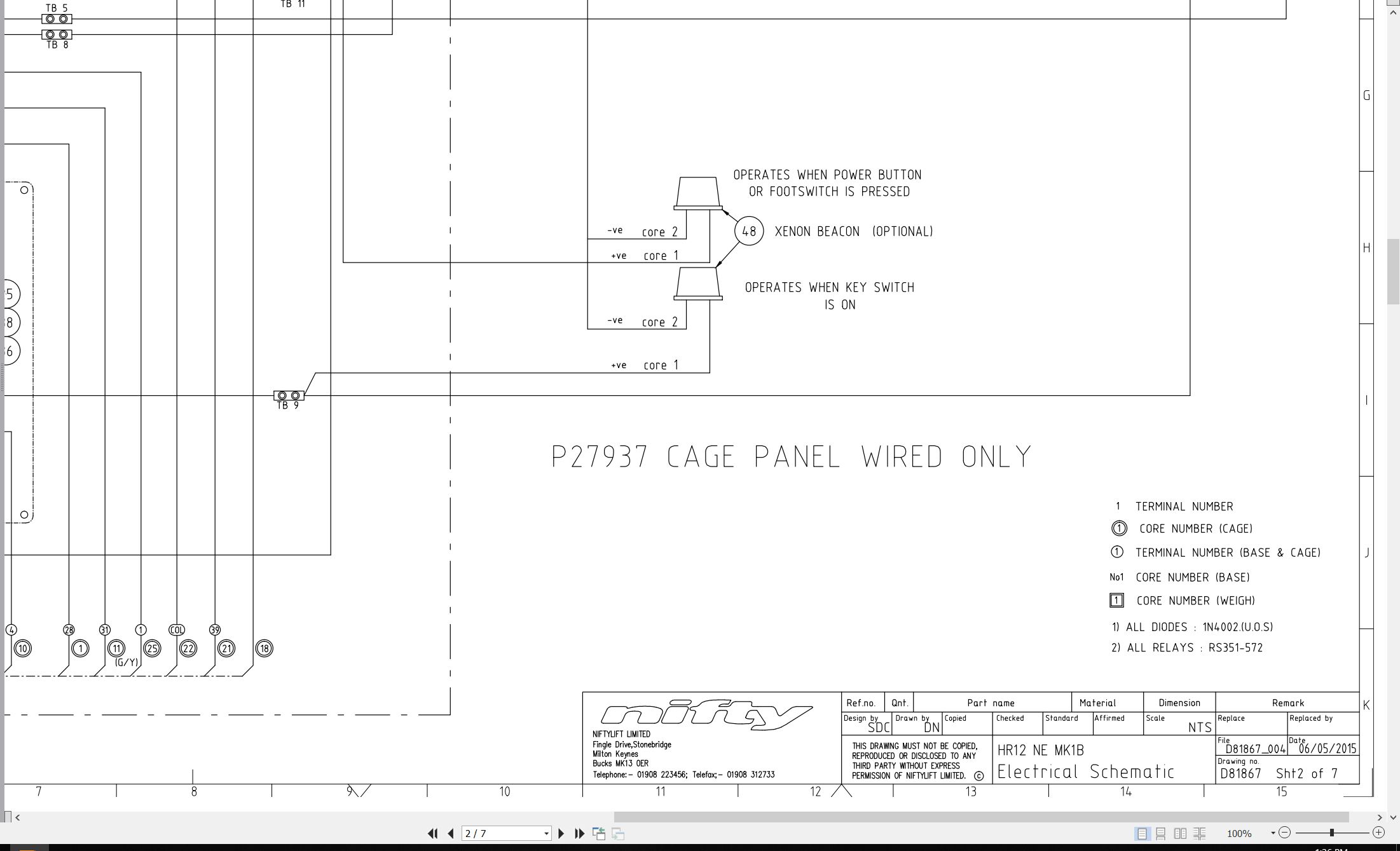
04_HR12 NE MK1B ELECTRICAL SCHEMATIC D81867 (issue 004) 36978.pdf (7 Pages)
05_HR10 12 SP26 34 OPERATING MANUAL UK USA M50192 (issue 017) 36978.pdf (58 Pages)
06_HR12 2×4 PARTS MANUAL M50510 (issue 006) 36978.pdf (102 Pages)
Contents:
chassis assembly
1.1 Base assembly – P/D/PE/DE
1.2 Base assembly – Electric
1.3 Bonnets/Covers/Guards
1.4 Steering assembly
1.5 Front hub assembly
1.6 Power pack
1.7 Drive control valve
1.8 Diesel engine (Part 1)
1.9 Diesel engine (Part 2)
1.10 Diesel box
1.11 Anderson connector
1.12 Generator assembly (Option)
superstructure
2.1 Control station – Base
2.2 Slew assembly
2.3 Control valve assembly (3 spool)
2.4 Control valve assembly (4 spool)
2.5 Button box assembly
2.6 Control box
2.7 Dual voltage charger box
2.8 Battery charger
boom assemblies
3.1 Booms assembly
3.2 Lift cylinder
3.3 Levelling cylinder
3.4 Telescope cylinder
3.5 Energy chain
cage assembly
4.1 Cage assembly
4.2 SiOPS assembly
4.3 Cage weigh assembly – Load Cell
4.4 Control box – Cage
4.5 Control valve – Cage
labelling
5.1 Label locations
5.2 Label locations SP34 (USA)
Labels 1 to 31
Labels 32 to 46
07_HR12 N SERVICE MANUAL M50606 (issue 001) 36978.pdf (64 Pages)
Contents:
1 Introduction and general information
1.1 Foreword
1.1.1 Defined maintenance terms
1.2 Warranty
1.3 Scope
1.4 General maintenance information
1.4.1 Pre-maintenance checks
1.4.2 Maintenance information
1.4.3 Frequent inspection
1.4.4 Annual inspection
1.5 Maintenance safety information
1.5.1 Personal injury prevention
1.5.2 Machine damage prevention
1.5.3 Diesel system safety
1.5.4 Electrical safety
1.5.5 Hydraulic safety
1.5.6 Environmental awareness
2 Specifications
2.1 Engine specifications
2.2 Gearbox specifications
2.3 Function times
2.4 Fluid properties
2.4.1 Fluid volumes
2.4.2 Engine oil specifications
2.4.3 Gearbox oil specifications
2.4.4 Hydraulic oil specifications
2.4.5 Hydraulic pressure settings
2.5 Tyre specifications
2.6 Torque settings
2.6.1 Torque settings – Kubota OC60 and OC95 engines
2.7 Hydraulic hose and fitting torque specifications
3 Preventative maintenance
3.1 Maintenance schedules
3.1.1 Engine maintenance
3.1.2 Machine maintenance
3.1.3 Engine oil level check
3.1.4 Engine oil replace
3.1.5 Engine oil strainer clean – Diesel
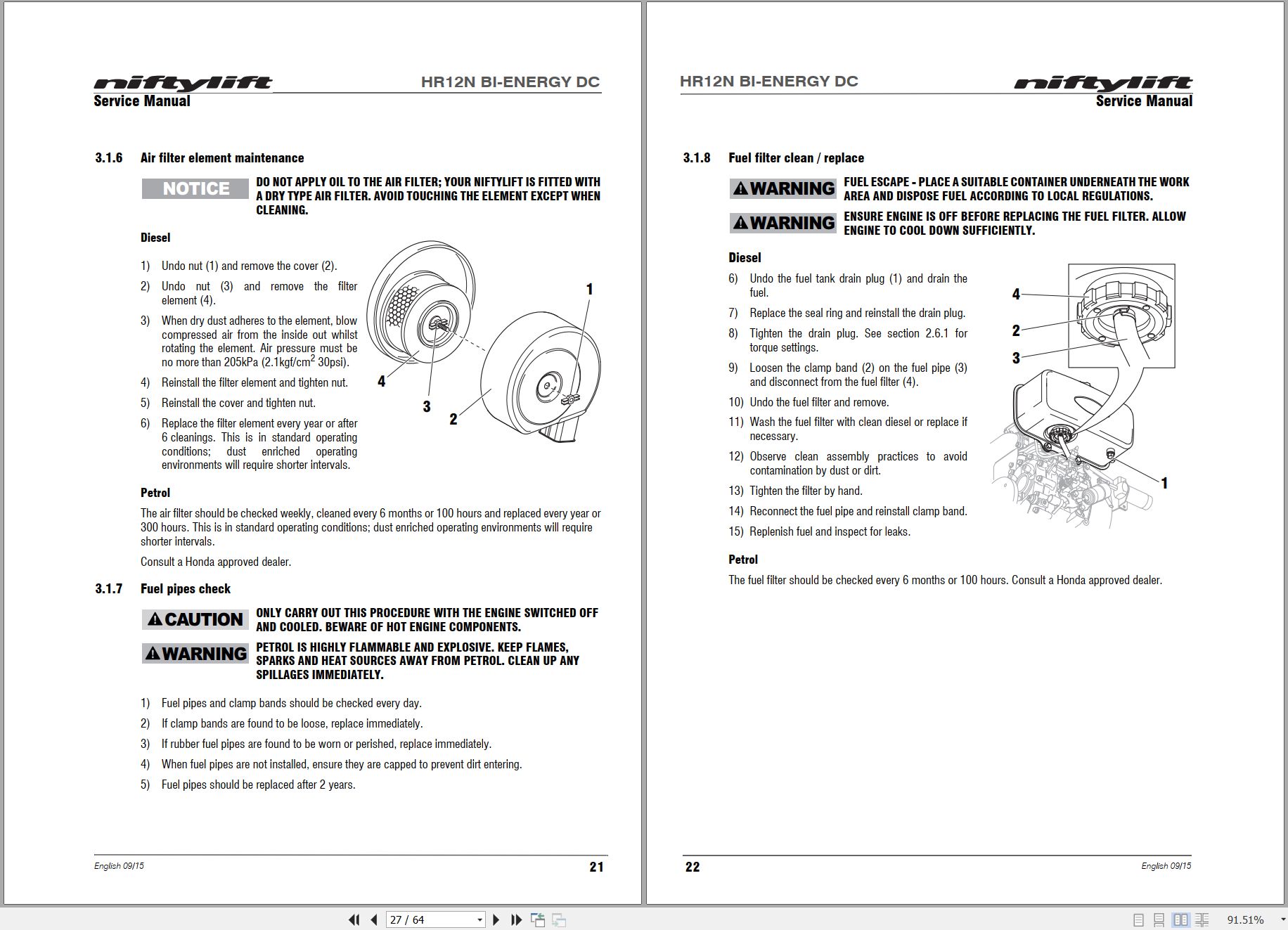
3.1.6 Air filter element maintenance
3.1.7 Fuel pipes check
3.1.8 Fuel filter clean / replace
3.1.9 Spark plug check
3.1.10 Exhaust system inspect
3.2 Drive hub gearbox
3.2.1 Oil replace
3.2.2 Bleeding air from the braking circuit
3.3 Batteries
3.3.1 Condition check (daily)
3.3.2 Condition check (weekly) – excludes AGM batteries
3.3.3 Storage
3.4 Inverter / generator and power to cage options
3.4.1 Condition check (daily)
3.5 Hydraulic oil
3.5.1 Level check (weekly)
3.5.2 Pressure filter check (weekly)
3.5.3 Hydraulic oil and filters replace
3.6 Telescopic boom
3.6.1 Wear pad check (monthly)
3.6.2 Hose trunking and energy chain check (weekly)
3.6.3 Boom pivot bushes lubricate (annually)
3.6.4 Boom pivot pin check (daily)
3.7 Boom rotation gear
3.7.1 Slew gear engagement check (monthly)
3.7.2 Slew ring lubrication (monthly)
3.7.3 Slew ring bolts check (yearly)
3.8 Front axle
3.8.1 Front wheel hub bushes (yearly)
3.9 Chassis
3.9.1 Earth strap check (daily)
3.10 Wheels and tyres
3.10.1 Wheel bolt torque (monthly)
4 Repair procedures
4.1 General
4.1.1 Fuses
4.2 Platform/Cage
4.2.1 Footswitch – contact switch replace
4.3 Booms
4.3.1 Energy chain link
4.4 Base Assembly
4.4.1 Engine exhaust
4.4.2 Steer cylinder
5 System overview
5.1 Introduction
5.1.1 Power system
5.1.2 DC electric system
5.2 Battery charging
5.2.1 Battery charging – extension leads
5.3 Bi-energy system
5.3.1 Duty selector
5.4 Boom system
5.4.1 Boom switch
5.5 Drive system
5.5.1 Drive Control Valve (DCV)
5.5.2 Brake Release Valve
5.6 Hydraulic system overview
5.7 Steering
5.8 Electrical control system overview
5.9 Control logic
6 Troubleshooting guide
6.1 Trouble shooting information
6.2 Platform function fault finding
6.3 Engine fault finding
6.3.1 Diesel engine
6.3.2 Petrol engine
6.4 Gearbox fault finding

REALEASE :
REALEASE :

REALEASE :
REALEASE :

REALEASE :
REALEASE :

REALEASE :
REALEASE :

REALEASE :
REALEASE :

REALEASE :
REALEASE :

REALEASE :
REALEASE :

REALEASE :
REALEASE :
 Automotive - Heavy Equipment - Truck & Bus - Forklift - Crane