
1 ITEMVIEW CART

Total: 60.00

Expert Support
Full Speed
100% Working
30 USD
List of Files:
01_DIAGRAM, HR15 17NDE TRAY MAIN WIRING D80330 (issue 009) 21745.pdf (1 Pages)
02_DIAGRAM, HR15 17NDE TRAY CABLE KIT D80335 (issue 006) 21745.pdf (1 Pages)
03_WIRING LOOM – HR15NDE TRAY D80364 (issue 008) 21745.pdf (1 Pages)
04_INSTALLATION INSTRUCTIONS D80877 (issue 003) 21745.pdf (1 Pages)
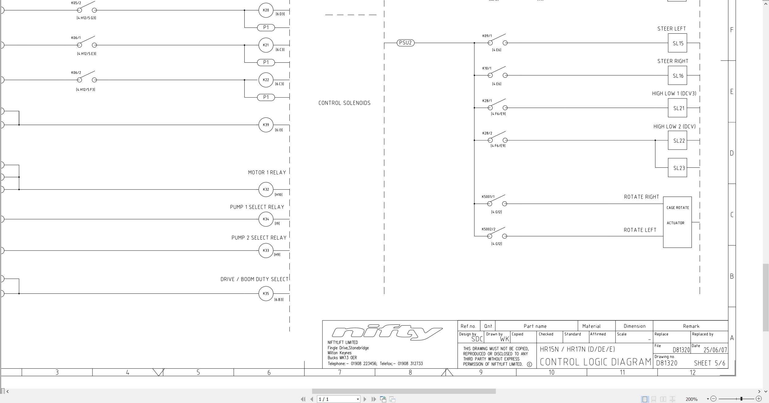
05_CONTROL LOGIC HR15 17N DE D E D81320 (issue 005) 21745.pdf (1 Pages)
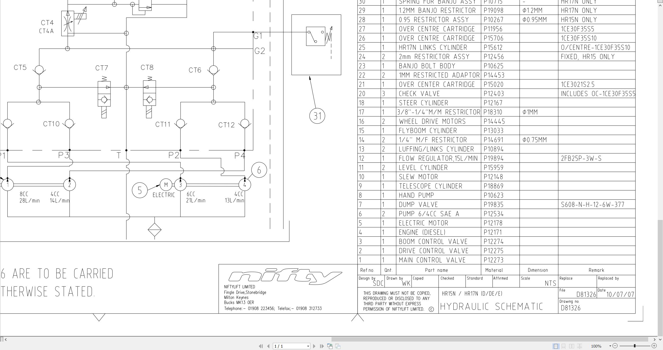
06_HYDRAULIC SCHEMATIC HR15 17N D E DE D81326 (issue 009) 21745.pdf (1 Pages)
07_CAGE BOX WIRING D81454 (issue 001) 21745.pdf (1 Pages)
08_CAGE LOOM LENGTHS D81458 (issue 001) 21745.pdf (1 Pages)
09_HR15N 17N SP45N 50N PARTS MANUAL M50200 (issue 004) 21745.pdf (104 Pages)
Contents:
chassis assembly
1.1 Base assembly
1.2 Axle assembly (Front)
1.3 Axle assembly (Rear)
1.4 Wheel hub assembly
1.5 Power tray assembly (Bi-energy)
1.6 Power tray assembly (DC)
1.7 Diesel engine – Part 1
1.8 Diesel engine – Part 2
1.9 Control box
1.10 Valveblock assembly – Transmission (DCV)
1.11 Valveblock assembly – Pump control
1.12 Anderson connector
1.13 Covers and guards
superstructure
2.1 Superstructure assembly
2.2 Base control assembly
2.3 Valveblock assembly
2.4 Control box assembly
2.5 Slew assembly
2.6 Battery charger (UK)
2.7 Battery charger (European)
2.8 Auto power inlet unit (UK)
boom assemblies
3.1 Telescope assembly
3.2 Links assembly (HR15N/SP45N)
3.3 Links assembly (HR17N/SP50N)
3.4 Lift & luffing cylinders
3.5 Energy chain
cage assembly
4.1 Cage assembly
4.2 Flyboom assembly
4.3 Flyboom cylinder
4.4 Levelling cylinder
4.5 Control panel assembly
labelling
5.1 Label locations (Part 1)
5.2 Label locations (Part 2)
Labels (1 -31)
Labels (33-37)
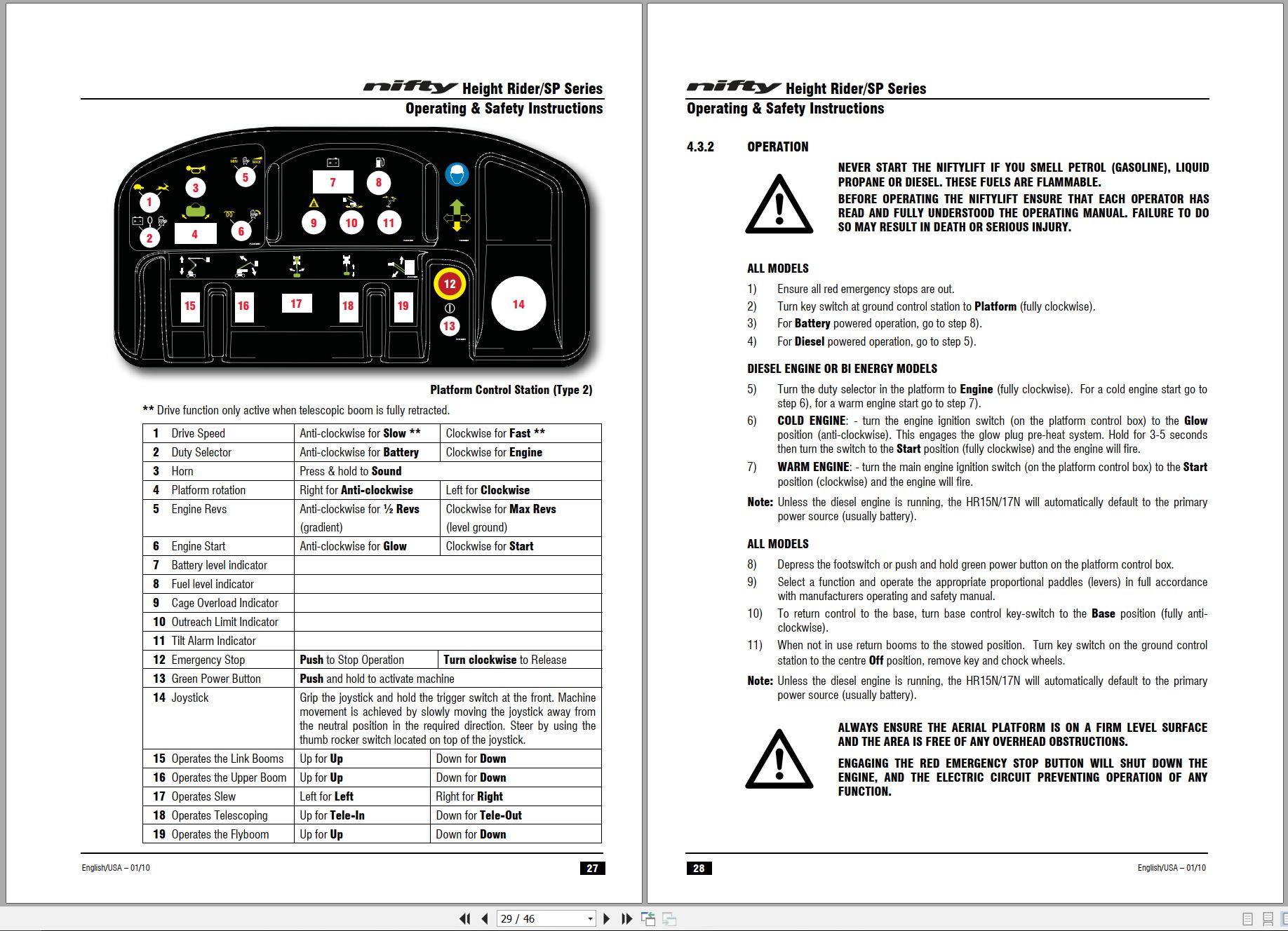
10_HR15N 17NSP45 50 OPERATING MANUAL UK USA M50201 (issue 007) 21745.pdf (46 Pages)
Contents:
4.5.2 FUNCTION
4.5.3 TESTING
4.5.4 CALIBRATION
4.5.5 INSPECTION
4.5.6 MAINTENANCE
4.5.7 REPLACEMENT
11_Kubota D722 Z482 Operators Manual And Wiring Diagram M50291 (issue 001) 21745 16676-8961-7.pdf (38 Pages)
Contents:
Contents
Safe Operation
1. Servicing
2. Part names
3. Pre-operation Check
4. Operating the Engine
Normal Starting
Cold Weather Starting
Stopping the Engine
Checks during Operation
Reversed engine running
5. Maintenance
Service Intervals
6. Periodic Service
Fuel
Engine Oil
Radiator
Air Cleaner
Battery
Electric Wiring
Fan belt
7. Carriage & Storage
8. Troubleshooting
9. Specifications
10. Wiring Diagram

REALEASE :
REALEASE :

REALEASE :
REALEASE :

REALEASE :
REALEASE :

REALEASE :
REALEASE :

REALEASE :
REALEASE :

REALEASE :
REALEASE :

REALEASE :
REALEASE :

REALEASE :
REALEASE :
 Automotive - Heavy Equipment - Truck & Bus - Forklift - Crane