
6 ITEMSVIEW CART


Total: 420.00

Expert Support
Full Speed
100% Working
40 USD
List of Files:
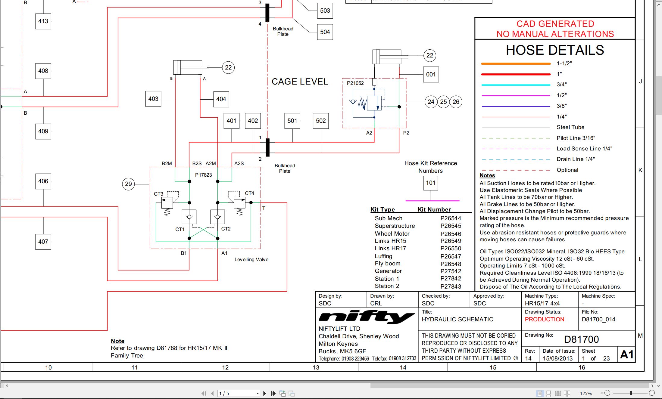
01_HYDRAULIC SCHEMATIC D81700 (issue 014) 43988.pdf (5 Pages)
Contents:
D81700_014
Schematics
D81700_Sht1
D81700_Sht2
D81700_Sht3
BOMS
D81700_Sht4
D81700_Sht5
02_SCHEMATIC, ELECTRICAL D81749 (issue 004) 43988.pdf (6 Pages)
03_MACHINE WIRED LAYOUT D81750 (issue 001) 43988.pdf (2 Pages)
04_HR15 17 HYBRID DIESEL MK2 LIFTING POINTS D81790 (issue 001) 43988.pdf (2 Pages)
05_Kubota D722 Z482 Operators Manual M50291 (issue 002) 43988 1J090-8916-1.pdf (39 Pages)
Contents:
E.pdf
SAFE OPERATION
SERVICING OF THE ENGINE
NAMES OF PARTS
PRE-OPERATION CHECK
BREAK-IN
DAILY CHECK
To prevent trouble from occurring, it is important to know the conditions of the engine well. Che…
OPERATING THE ENGINE
STARTING THE ENGINE(NORMAL)
COLD WEATHER STARTING
STOPPING THE ENGINE
CHECKS DURING OPERATION
REVERSED ENGINE REVOLUTION AND REMEDIES
MAINTENANCE
SERVICE INTERVALS
PERIODIC SERVICE
FUEL
ENGINE OIL
RADIATOR
AIR CLEANER
ELECTRIC WIRING
FAN BELT
CARRIAGE AND STORAGE
CARRIAGE
STORAGE
TROUBLESHOOTING
If the engine does not function properly, use the following chart to identify and correct the cause.
SPECIFICATIONS
WIRING DIAGRAMS
06_HR15 17 HYBRID OPERATING MANUAL UK M50381 (issue 005) 43988.pdf (52 Pages)
Contents:
1 Introduction and General Information
1.1 FOREWORD
1.2 SCOPE
1.3 INTRODUCING THE HEIGHT RIDER SELF-PROPELLED (SP) SERIES
1.4 GENERAL SPECIFICATION
1.5 IDENTIFICATION (UK PLATE)
1.6 EC DECLARATION OF CONFORMITY (Typical)
2 Safety
2.1 MANDATORY PRECAUTIONS
2.2 ENVIRONMENTAL LIMITATIONS
2.3 NOISE AND VIBRATION
2.4 TEST REPORT
3 Preparation and Inspection
3.1 UNPACKING
3.2 PREPARATION FOR USE
3.3 PRE-OPERATIONAL SAFETY CHECK SCHEDULES
3.4 PLACARD, DECALS & INSTALLATION (UK SPEC)
3.5 TORQUE REQUIREMENTS
4 Operation
4.1 CONTROL CIRCUIT COMPONENTS
4.2 GROUND CONTROL OPERATION
4.3 PLATFORM CONTROL OPERATION
4.4 DRIVING CONTROLS
4.5 CAGE WEIGH SYSTEM
4.6 BATTERIES AND CHARGING
4.7 TRANSPORTING, TOWING, CRANEAGE, STORAGE AND SETTING TO WORK
5 Emergency Controls
5.1 GENERAL
5.2 IN THE EVENT OF AN INCAPACITATED OPERATOR
5.3 IN THE EVENT OF MACHINE FAILURE
5.4 INCIDENT NOTIFICATION
6 Responsibilities
6.1 CHANGES IN OWNERSHIP
6.2 MANUAL OF RESPONSIBILITIES (USA only)
6.3 INSPECTION/SERVICE/PRE-HIRE CHECK LIST
Appendix A
07_HR15 17 (SP45 50) H D MK2 PARTS MANUAL M50500 (issue 003) 43988.pdf (110 Pages)
Contents:
Front Cover
Parts Order Form
Contents
chassis assembly
1.1 Base assembly
1.2 Front axle assembly
1.3 Charger inlet (Hybrid)
1.4 Generator assembly (Option)
1.5 Oil cooler assembly (Option)
1.6 Control box – Oil cooler
1.7 Inverter (Option)
1.8 Drive valve block
superstructure
2.1 Superstructure (1)
2.2 Superstructure (2)
2.3 Power tray assembly (Hybrid)
2.4 Power tray assembly (Diesel)
2.5 Diesel engine (Hybrid) – part 1
2.6 Diesel engine (Hybrid) – part 2
2.7 Diesel engine (Diesel)
2.8 Diesel engine (Hybrid) – D902
2.9 Slew assembly
2.10 Base control assembly
2.11 Engine box assembly (Hybrid)
2.12 Engine box assembly (Diesel)
2.13 Pump control valve
boom assemblies
3.1 Telescope assembly (Part 1)
3.2 Telescope assembly (Part 2)
3.3 Links assembly (HR15/SP45)
3.4 Links assembly (HR17/SP50)
3.5 Lift & luffing cylinders
3.6 Levelling cylinder
3.7 Energy chain
3.8 Levelling valve block
cage and flyboom
4.1 toughcage assembly
4.2 cage console assembly
4.3 SiOPS assembly
4.4 cage rotate assembly
4.5 flyboom assembly
4.6 flyboom cylinder
4.7 control panel assembly
labelling
5.1 Label locations
Figure 5.1
Labels 1 to 31
Labels 32 to 42
08_HR15 17 4×4 MK2 SERVICE MANUAL M50600 (issue 001) 43988.pdf (76 Pages)
Contents:
1 Introduction and General Information
1.1 Foreword
1.1.1 Defined Maintenance Terms
1.2 Warranty
1.3 Scope
1.4 General Maintenance Information
1.4.1 Pre-Maintenance Checks
1.4.2 Maintenance Information
1.4.3 Frequent Inspection
1.5 Maintenance Safety Information
1.5.1 Personal Injury Prevention
1.5.2 Machine Damage Prevention
1.5.3 Diesel System Safety
1.5.4 Hydraulic Safety
1.5.5 Electrical Safety
1.5.6 Environmental Awareness
2 Specifications
2.1 Engine Specifications
2.2 Gearbox Specifications
2.3 Function Times
2.4 Fluid Properties
2.4.1 Fluid Volumes
2.4.2 Engine Oil Specifications
2.4.3 Gearbox Oil Specifications
2.4.4 Hydraulic Oil Specifications
2.4.5 Engine Coolant Specifications
2.4.6 Hydraulic Pressure Settings
2.5 Tyre Specifications
2.6 Torque Settings
2.7 Hydraulic Hose And Fitting Torque Specifications
3 Preventative Maintenance
3.1 Maintenance Schedules
3.1.1 Maintenance Procedures and Intervals
3.1.2 Engine Oil Level Check
3.1.3 Engine Oil Replace
3.1.4 Engine Oil Filter Replace
3.1.5 Engine Coolant Level Check
3.1.6 Coolant Replace
3.1.7 Coolant Hoses and Clamp Bands Check
3.1.8 Air Filter Element Maintenance
3.1.9 Fuel Pipes Check
3.1.10 In-line Fuel Filter Replace
3.1.11 Fuel Filter (Cartridge Type) Replace
3.1.12 Fuel Filter and Water Separator Clean/Replace
3.1.13 Bleeding Air From The Fuel System
3.1.14 Exhaust System Inspect
3.1.15 Fan Belt Check (Every 100 Hours)
3.2 Drive Hub Gearbox
3.2.1 Oil Replace
3.2.2 Bleeding Air From The Braking Circuit
3.3 Batteries
3.3.1 Condition Check (Daily)
3.3.2 Condition Check (Weekly) – Excludes AGM Batteries
3.4 Hydraulic Oil
3.4.1 Level Check (Weekly)
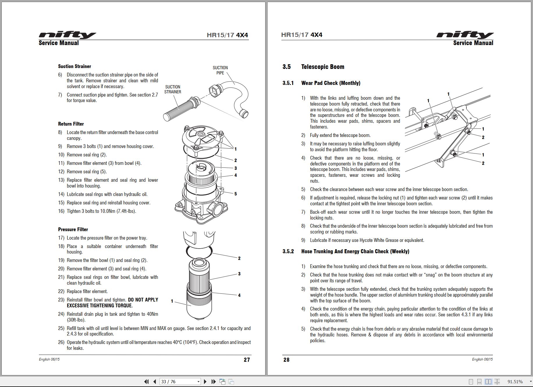
3.4.2 Return Filter Check (Monthly)
3.4.3 Pressure Filter Check (Weekly)
3.4.4 Hydraulic Oil And Filters Replace
3.5 Telescopic Boom
3.5.1 Wear Pad Check (Monthly)
3.5.2 Hose Trunking And Energy Chain Check (Weekly)
3.5.3 Lubricate Boom Pivot Bushes
3.5.4 Boom Pivot Pin Check (Daily)
3.6 Boom Rotation Gear
3.6.1 Slew Gear Engagement Check (Monthly)
3.6.2 Slew Ring Lubrication (Monthly)
3.6.3 Slew Ring Bolts Check (Yearly)
4 Repair Procedures
4.1 General
4.1.1 Fuses
4.2 Platform/Cage
4.2.1 Footswitch – Contact Switch Replace
4.3 Booms
4.3.1 Energy Chain Link
4.4 Power tray
4.4.1 Exhaust
4.4.2 Fan Belt
4.5 Base Assembly
4.5.1 Steer Cylinder
5 System Overview
5.1 Introduction
5.1.1 Hybrid System
5.1.2 Diesel System
5.2 Hybrid Operation
5.3 Boom System
5.4 Drive System
5.4.1 Hybrid
5.5 Charging System And Batteries
5.5.1 Charging System – Hybrid
5.5.2 Charging System – Diesel
5.6 Hydraulic System Overview
5.7 Load Sensing Pump
5.8 Valve Block Assembly
5.9 Diff Lock
5.10 Brake Release
5.11 Steering
5.12 Boom Control Valve
5.13 Electrical Control System Overview
5.14 Control Logic
5.16 Controller
5.17 Niftylift Diagnostic Unit
6 Troubleshooting guide
6.1 Trouble Shooting Information
6.2 Platform Function Fault Finding
6.3 Engine Fault Finding
6.4 Gearbox Fault Finding
6.5 Fault Code Display
6.6 Motor Controller Fault Codes
Blank Page

REALEASE :
REALEASE :

REALEASE :
REALEASE :

REALEASE :
REALEASE :

REALEASE :
REALEASE :

REALEASE :
REALEASE :

REALEASE :
REALEASE :

REALEASE :
REALEASE :

REALEASE :
REALEASE :
 Automotive - Heavy Equipment - Truck & Bus - Forklift - Crane