
5 ITEMSVIEW CART


Total: 160.00

Expert Support
Full Speed
100% Working
40 USD
List of Files:
01_TRAY MAIN WIRING HR15 17NE D80318 (issue 008) 22235.pdf (1 Pages)
02_TRAY BOX WIRING HR15 17NE D80319 (issue 005) 22235.pdf (1 Pages)
03_DIAGRAM, HR15NE WIRING LOOM D80334 (issue 005) 22235.pdf (1 Pages)
04_INSTALLATION INSTRUCTIONS D80877 (issue 003) 22235.pdf (1 Pages)
05_CONTROL LOGIC HR15 17N DE D E D81320 (issue 005) 22235.pdf (1 Pages)
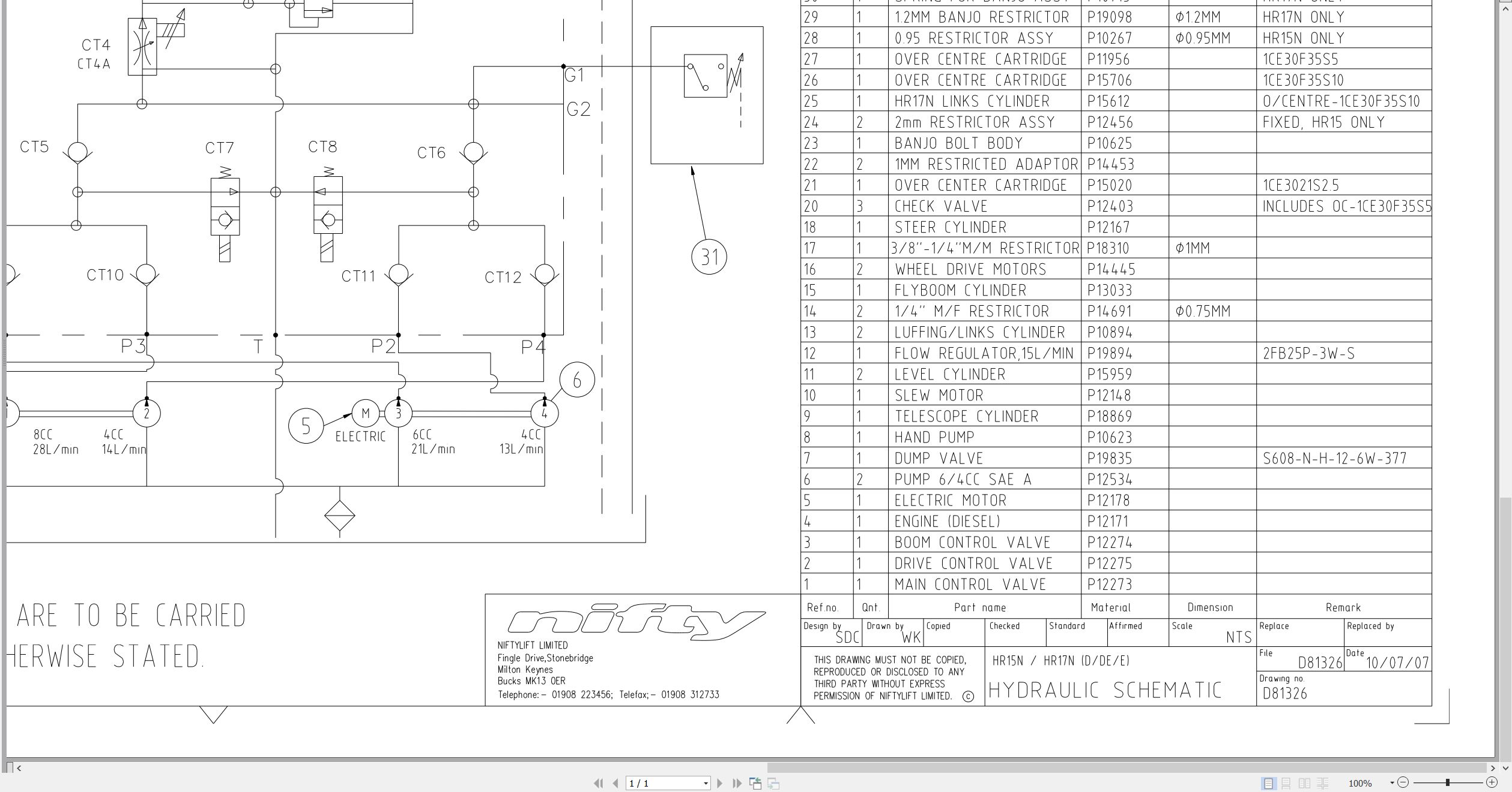
06_HYDRAULIC SCHEMATIC HR15 17N D E DE D81326 (issue 009) 22235.pdf (1 Pages)
07_CAGE BOX WIRING D81454 (issue 002) 22235.pdf (4 Pages)
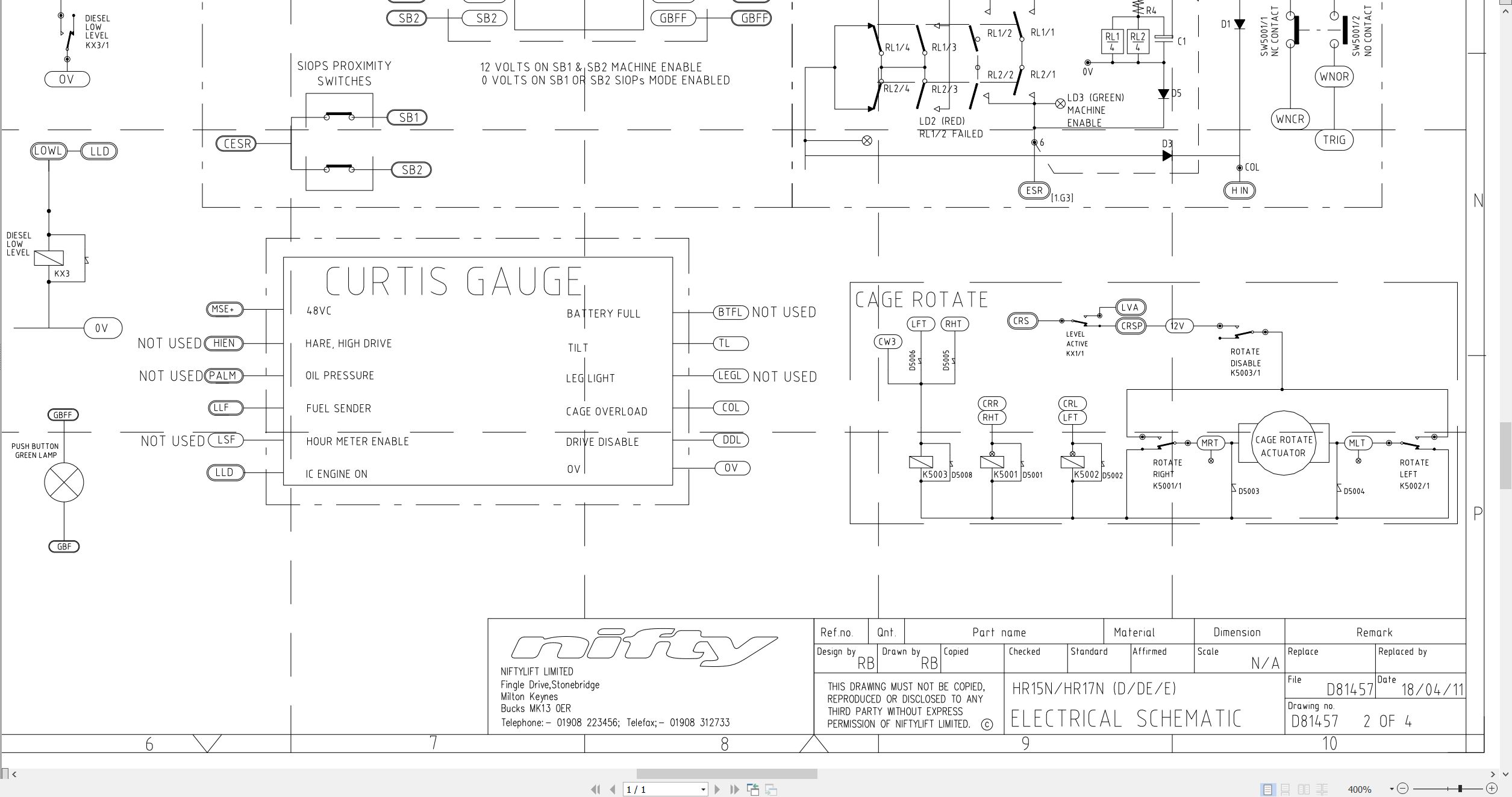
08_ELECTRICAL SCHEMATIC HR15 17N D DE E D81457 (issue 001) 22235.pdf (1 Pages)
09_HR15N 17N SP45N 50N PARTS MANUAL M50200 (issue 005) 22235.pdf (110 Pages)
Contents:
Introduction
Parts Order Form
Contents
chassis assembly
1.1 Base assembly
1.2 Axle assembly (Front)
1.3 Axle assembly (Rear)
1.4 Wheel hub assembly
1.5 Power tray assembly (Bi-energy)
1.6 Power tray assembly (DC)
1.7 Diesel engine – Part 1
1.8 Diesel engine – Part 2
1.9 Control box
1.10 Valveblock assembly – Transmission (DCV)
1.11 Valveblock assembly – Pump control
1.12 Anderson connector
1.13 Covers and guards
superstructure
2.1 Superstructure assembly
2.2 Base control assembly
2.3 Valveblock assembly
2.4 Control box assembly
2.5 Slew assembly
2.6 Battery charger (UK)
2.7 Battery charger (European)
2.8 Auto power inlet unit (UK)
boom assemblies
3.1 Telescope assembly
3.2 Links assembly (HR15N/SP45N)
3.3 Links assembly (HR17N/SP50N)
3.4 Lift & luffing cylinders
3.5 Energy chain
cage assembly
4.1 Cage assembly
4.2 Cage console assembly
4.3 SiOPS assembly
4.4 Flyboom assembly
4.5 Flyboom cylinder
4.6 Levelling cylinder
4.7 Control panel assembly
4.8 Control box assembly
labelling
5.1 Label locations (Part 1)
5.2 Label locations (Part 2)
Labels (1 -31)
Labels (33-37)
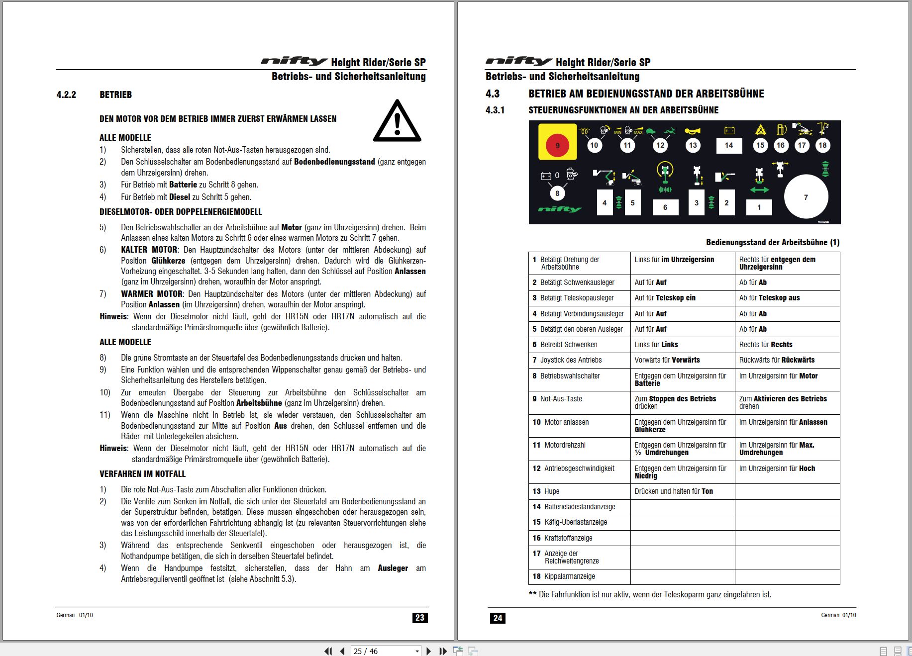
10_HR15N 17N OPERATING MANUAL GERMAN M50205 (issue 007) 22235.pdf (46 Pages)

REALEASE :
REALEASE :

REALEASE :
REALEASE :

REALEASE :
REALEASE :

REALEASE :
REALEASE :

REALEASE :
REALEASE :

REALEASE :
REALEASE :

REALEASE :
REALEASE :

REALEASE :
REALEASE :
 Automotive - Heavy Equipment - Truck & Bus - Forklift - Crane