
0 ITEMSVIEW CART


✓
Expert Support
✓
Full Speed
✓
100% Working
NIFTYLIFT Articulating Boom Lifts HR21 26424 Operating Parts Manual And Diagram 2013
Size: 20.24 MB
Format: PDF
Language: English
Brand: NIFTYLIFT
Type of Machine: Articulating Boom Lifts
Type of Manual: Service Manual, Operating Manual, Inspection Manual, Parts Manual, Electrical Schematic, Hydraulic Schematic,
Model: NIFTYLIFT HR21 Articulating Boom Lifts
Serial Number: 26424
Publication Date: 2013
40 USD
- Description
Description
List of Files:
01_MAIN TRAY WIRING SCHEMATIC D80399 (issue 003) 26424.pdf (1 Pages)
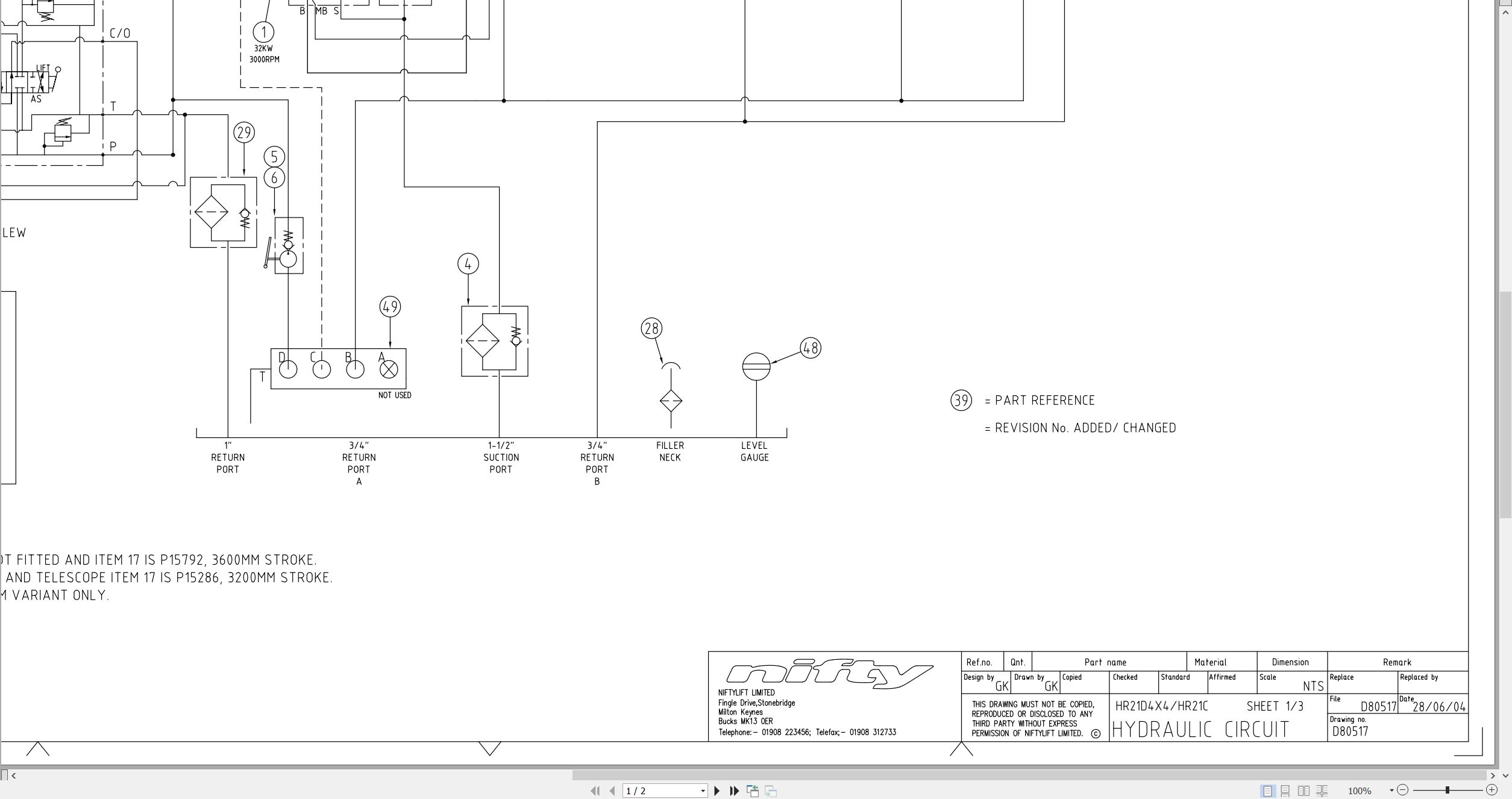
02_SCHEMATIC – HYDRAULIC HR21 4X4 D80517 (issue 016) 26424.pdf (2 Pages)
03_WIRING DIAGRAM HR21 TRAY D80568 (issue 002) 26424.pdf (1 Pages)
04_DIAGRAM FUEL LEVEL SWITCH INSTALLATION D80892 (issue 002) 26424.pdf (1 Pages)
05_DIAGRAM LIFTING POINTS HR21 ALL MODELS D80938 (issue 004) 26424.pdf (2 Pages)
06_HOSE DIAGRAM HR21 DRIVE CIRCUIT D81256 (issue 002) 26424.pdf (1 Pages)
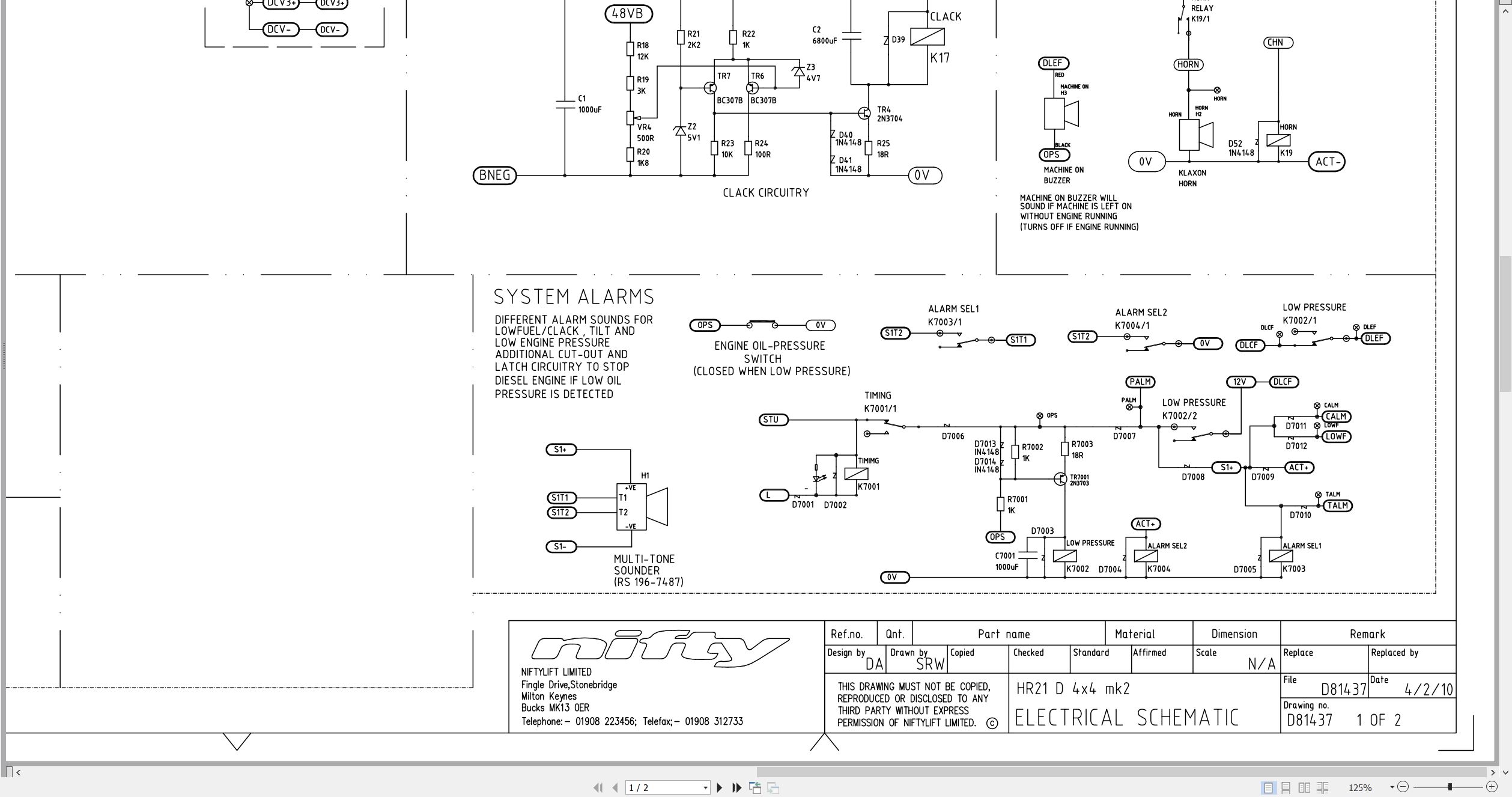
07_MACHINE ELECTRICAL SCHEMATIC D81437 (issue 002) 26424.pdf (2 Pages)
08_HR21 SP64 4×4 PARTS MANUAL M50240 (issue 006) 26424.pdf (100 Pages)
Contents:
Chassis Assembly
1.1 Base Assembly
1.2 Axle Assembly (Front)
1.3 Axle Assembly (Rear)
1.4 Diesel Tank Assembly
1.5 Pump Control Valve Block
1.6 Oil Cooler Assembly (Option)
1.7 Control Box – Oil Cooler
Superstructure
2.1 Superstructure Assembly
2.2 Power Tray Assembly
2.3 Diesel Engine – Part 1
2.4 Diesel Engine – Part 2
2.5 Control Valve (6 Spool)
2.6 Base Control Box
2.7 Pcb Control Box
2.8 Main Valve Block
2.9 Suspension Valve Block
Boom Assemblies
3.1 Links Assembly
3.2 Telescope Assembly (Part 1)
3.3 Telescope Assembly (Part 2)
3.4 Lift & Luffing Cylinder
3.5 Levelling Cylinders
3.6 Levelling Valve
3.7 Energy Chain
Cage And Flyboom
4.1 Toughcage Assembly
4.2 Cage Console Assembly
4.3 Siops Assembly
4.4 Cage Rotate Assembly
4.5 Flyboom Assembly
4.6 Flyboom Cylinder
4.7 Control Panel Assembly
4.8 Control Valve (6 Spool)
Labelling
5.1 Label Locations
Figure 5.1
Labels (1 -32)
Labels (33-42)
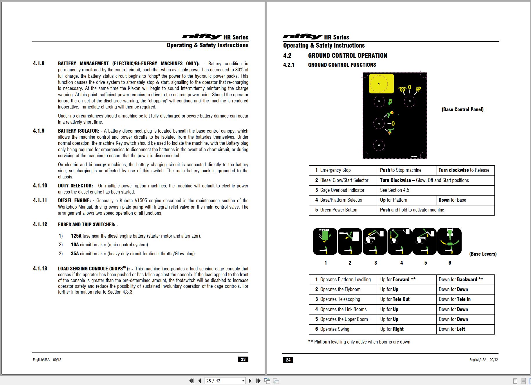
09_HR21 SP64 4×4 OPERATING MANUAL UK USA M50241 (issue 007) 26424.pdf (42 Pages)
10_CHAIN INSPECTION MANUAL UK USA M50280 (issue 002) 26424.pdf (13 Pages)
Contents:
Blank Page
11_Kubota V1505 Operators Manual M50292 (issue 001) 26424 16622-8916-8.pdf (38 Pages)
Related Products
-
NIFTYLIFT Towable Boom Lifts TM50 57219 Operating Service Parts Manual And Diagram 2025
50 USDSize: 27.83 MBFormat: PDFLanguage: EnglishBrand: NIFTYLIFTType of Machine: Towable Boom LiftsType of Manual: Service Manual, Operating Manual, Parts Manual, Electrical Schematic, Hydraulic Schematic,Model: NIFTYLIFT TM50 Towable Boom LiftsSerial Number: 57219Publication Date: 2025
REALEASE :
REALEASE :
-
NIFTYLIFT Towable Boom Lifts TM50 58728 Operating Service Parts Manual And Diagram 2025
50 USDSize: 20.05 MBFormat: PDFLanguage: EnglishBrand: NIFTYLIFTType of Machine: Towable Boom LiftsType of Manual: Service Manual, Operating Manual, Parts Manual, Electrical Schematic, Hydraulic Schematic,Model: NIFTYLIFT TM50 Towable Boom LiftsSerial Number: 58728Publication Date: 2025
REALEASE :
REALEASE :
-
NIFTYLIFT Towable Boom Lifts TM64 55045 Operators Service Manual Diagram 2023
40 USDSize: 28.66 MBFormat: PDFLanguage: EnglishBrand: NIFTYLIFTType of Machine: Towable Boom LiftsType of Manual: Service Manual, Operating Manual, Parts Manual, Electrical SchematicModel: NIFTYLIFT TM64 Towable Boom LiftsSerial Number: 55045Publication Date: 2023
REALEASE :
REALEASE :
-
NIFTYLIFT Towable Boom Lifts TM50 56720 Operating Service Parts Manual And Diagram 2025
50 USDSize: 27.98 MBFormat: PDFLanguage: EnglishBrand: NIFTYLIFTType of Machine: Towable Boom LiftsType of Manual: Service Manual, Operating Manual, Parts Manual, Electrical Schematic, Hydraulic Schematic,Model: NIFTYLIFT TM50 Towable Boom LiftsSerial Number: 56720Publication Date: 2025
REALEASE :
REALEASE :
-
NIFTYLIFT Towable Boom Lifts TM50 56687 Operating Service Parts Manual And Diagram 2025
50 USDSize: 20.05 MBFormat: PDFLanguage: EnglishBrand: NIFTYLIFTType of Machine: Towable Boom LiftsType of Manual: Service Manual, Operating Manual, Parts Manual, Electrical Schematic, Hydraulic Schematic,Model: NIFTYLIFT TM50 Towable Boom LiftsSerial Number: 56687Publication Date: 2025
REALEASE :
REALEASE :
-
NIFTYLIFT Towable Boom Lifts TM64 55060 Operating Service Parts Manual And Diagram 2023
40 USDSize: 28.83 MBFormat: PDFLanguage: EnglishBrand: NIFTYLIFTType of Machine: Towable Boom LiftsType of Manual: Service Manual, Operating Manual, Parts Manual, Electrical Schematic, Hydraulic Schematic,Model: NIFTYLIFT TM64 Towable Boom LiftsSerial Number: 55060Publication Date: 2023
REALEASE :
REALEASE :
-
NIFTYLIFT Towable Boom Lifts TM64 52414 Operating Service Parts Manual And Diagram 2022
40 USDSize: 29.17 MBFormat: PDFLanguage: EnglishBrand: NIFTYLIFTType of Machine: Towable Boom LiftsType of Manual: Service Manual, Operating Manual, Parts Manual, Electrical Schematic, Hydraulic Schematic,Model: NIFTYLIFT TM64 Towable Boom LiftsSerial Number: 52414Publication Date: 2022
REALEASE :
REALEASE :
-
NIFTYLIFT Towable Boom Lifts TM64 56064 Operating Service Parts Manual And Diagram 2023
40 USDSize: 28.80 MBFormat: PDFLanguage: EnglishBrand: NIFTYLIFTType of Machine: Towable Boom LiftsType of Manual: Service Manual, Operating Manual, Inspection Manual, Parts Manual, Electrical Schematic, Hydraulic Schematic,Model: NIFTYLIFT TM64 Towable Boom LiftsSerial Number: 56064Publication Date: 2023
REALEASE :
REALEASE :