
0 ITEMSVIEW CART


✓
Expert Support
✓
Full Speed
✓
100% Working
NIFTYLIFT Articulating Boom Lifts HR21 MK2 45420 Operating Service Parts Manual And Diagram 2019 EN DE
Size: 39.59 MB
Format: PDF
Language: English, German
Brand: NIFTYLIFT
Type of Machine: Articulating Boom Lifts
Type of Manual: Service Manual, Operating Manual, Inspection Manual, Parts Manual, Electrical Schematic, Hydraulic Schematic
Model: NIFTYLIFT HR21 Articulating Boom Lifts
Serial Number: MK2
Publication Date: 2019
40 USD
- Description
Description
List of Files:
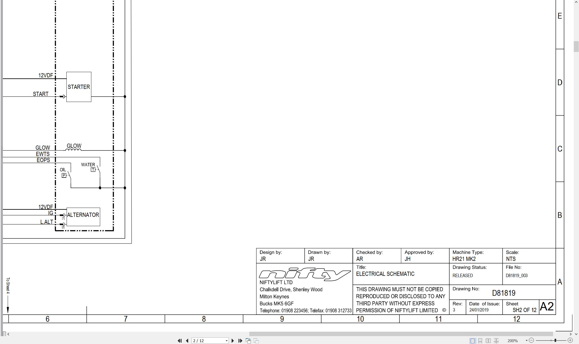
01_ELECTRICAL SCHEMATIC HR21 D81819 (issue 003) 45420.pdf (12 Pages)
02_LIFTING POINTS, HR21 MK2 D81980 (issue 002) 45420.pdf (2 Pages)
Contents:
Sheets and Views
D81980_002-English
D81980_002-French
03_WORKING ENVELOPE, HR21 MK2 D81981 (issue 002) 45420.pdf (2 Pages)
Contents:
Sheets and Views
D81981_002-MEETERS
D81981_002-FEET
04_STOWED DIMENSIONS, HR21 MK2 D81982 (issue 002) 45420.pdf (2 Pages)
Contents:
Sheets and Views
D81982_002-Steel Cage
D81982_002-Tough Cage
05_TRANSPORT & TIE DOWN, HR21 MK D81983 (issue 001) 45420.pdf (1 Pages)
06_TURNING CIRCLE, HR21 MK2 D81984 (issue 002) 45420.pdf (1 Pages)
Contents:
Sheets and Views
D81984-Layout
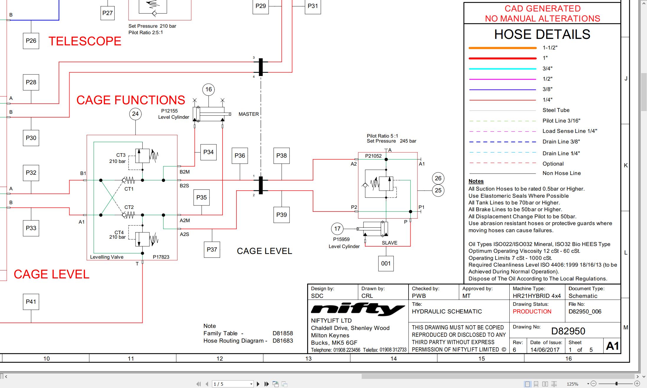
07_SCHEMATIC – HYDRAULIC HR21 MK2 HYBRID D82950 (issue 006) 45420.pdf (5 Pages)
Contents:
D82950_006
Schematics
D82950_Sht1
D82950_Sht2
D82950_Sht3
BOMS
D82950_Sht4
D82950_Sht5
08_CHAIN INSPECTION MANUAL GERMAN M50283 (issue 002) 45420.pdf (13 Pages)
Contents:
Blank Page
09_HR21 (SP64) MK2 PARTS MANUAL M50540 (issue 003) 45420.pdf (111 Pages)
Contents:
Front Cover
Parts Order Form
chassis assembly
1.1 Base Assembly
1.2 Axle Assembly (Front)
1.3 Axle Assembly (Rear)
1.4 Hydraulic Tray Assembly
1.5 Suspension Valve Block
1.6 Generator Assembly (Option)
1.7 Battery Pod Assembly – Lithium (Option)
Superstructure
2.1 Superstructure (1)
2.2 Superstructure (2)
2.3 Power Tray Assembly (Hybrid)
2.4 Power Tray Assembly (Diesel – Perkins)
2.5 Power Tray Assembly (Diesel – Kubota)
2.6 Diesel Engine (Hybrid) – Part 1
2.7 Diesel Engine (Hybrid) – Part 2
2.8 Diesel Engine (Diesel – Perkins)
2.9 Diesel Engine (Diesel – Kubota) – Part 1
2.10 Diesel Engine (Diesel – Kubota) – Part 2
2.11 Base Control Assembly
2.12 Track Unit (Niftylink)
Boom Assemblies
3.1 Links Assembly
3.2 Telescope Assembly (Part 1)
3.3 Telescope Assembly (Part 2)
3.4 Lift & Luffing Cylinders
3.5 Levelling Cylinders
3.6 Levelling Valve Assembly
3.7 Energy Chain
Cage And Flyboom
4.1 Toughcage Assembly
4.2 Cage Console Assembly
4.3 Siops Assembly
4.4 Cage Rotate Assembly
4.5 Flyboom Assembly
4.6 Flyboom Cylinder
4.7 Control Panel Assembly
Labelling
5.1 Label Locations
Figure 5.1
Labels 1 To 33
Labels 34 To 46
Chapter1_Iss02.Pdf
Chassis Assembly
1.1 Base Assembly
1.2 Axle Assembly (Front)
1.3 Axle Assembly (Rear)
1.4 Hydraulic Tray Assembly
1.5 Suspension Valve Block
1.6 Generator Assembly (Option)
1.7 Battery Pod Assembly – Lithium (Option)
1.8 Battery Charger Assemblies
10_HR21 MK2 OPERATING MANUAL (GERMAN) M50545 (issue 003) 45420.pdf (82 Pages)
Contents:
1 Einführung Und Allgemeine Informationen
1.1 Vorwort
1.2 Umfang
1.3 Vorstellung Der Height Rider Serie Mit Selbstantrieb (Sp)
1.4 Allgemeine Spezifikationen
1.5 Kennzeichnung (Typenschild Uk)
1.6 Eg-Konformitätserklärung (Typisch)
2 Sicherheit
2.1 Zwingend Notwendige Vorsichtsmassnahmen
2.2 Umwelteinschränkungen
2.3 Geräusche Und Vibrationen
2.4 Testbericht
3 Vorbereitung Und Inspektion
3.1 Auspacken
3.2 Vorbereitung Auf Die Nutzung
3.3 Sicherheitsüberprüfungen Vor Dem Betrieb
3.3.1 Tägliche Sicherheitsüberprüfung
3.3.2 Wöchentliche Sicherheitsüberprüfung
3.3.3 Monatliche Sicherheitsüberprüfung
3.3.4 Jährliche Sicherheitsüberprüfung
Toughcage
3.4 Anschläge, Klebebilder & Installation
3.5 Drehmomentvorgaben
4 Betrieb
4.1 Komponenten Des Steuerkreises
4.1.1 Bodensteuerung
4.1.2 Plattform
4.1.3 Chassis
4.1.4 Sicherungen
4.2 Betrieb Mit Bodensteuerung
4.2.1 Funktionen Der Bodensteuerung
4.2.2 Betrieb
4.3 Betrieb Mit Plattformsteuerung
4.3.1 Funktionen Der Plattformsteuerung
4.3.2 Anzeigebildschirm (Informationsbildschirm)
4.3.3 Informationspiktogramme
4.3.4 Menübildschirme
4.3.5 Betrieb
4.3.6 Siopstm – Belastung Erkennende Bedienkonsole
4.4 Fahrsteuerung
4.5 Korb-Wiegesystem
4.5.1 Wägezellen-Version
4.5.2 Kalibrierung, Inspektion Und Wartung
4.6 Batterien Und Aufladen Der Batterien (Hybrid)
4.7 Transport, Ziehen, Anheben Mit Einem Kran, Lagerung Und Vorbereitungsarbeiten
4.7.1 Transport
4.7.2 Ziehen
4.7.3 Anheben Mit Einem Kran
4.7.4 Lagerung
4.7.5 Vorbereitungsarbeiten
5 Notfallsteuerung
5.1 Allgemeines
5.2 Im Falle Eines Arbeitsunfähigen Bedieners
5.3 Im Falle Eines Maschinenausfalls
5.4 Melden Von Zwischenfällen
6 Verantwortlichkeiten
6.1 Wechsel Des Eigentümers
6.2 Checkliste Für Inspektion/Service/Vor Der Vermietung
Anhang A
Anhang B
11_HR21 MK2B SERVICE MANUAL UK M50648 (issue 001) 45420.pdf (112 Pages)
Contents:
1 Introduction and general information
1.1 Foreword
1.1.1 Defined maintenance terms
1.2 Warranty
1.3 Scope
1.4 General maintenance information
1.4.1 Pre-maintenance checks
1.4.2 Maintenance information
1.4.3 Frequent inspection
1.4.4 Annual inspection
1.5 Maintenance safety information
1.5.1 Personal injury prevention
1.5.2 Machine damage prevention
1.5.3 Diesel system safety
1.5.4 Hydraulic safety
1.5.5 Environmental awareness
1.5.6 Electrical safety
2 Specifications
2.1 Engine specifications
2.2 Gearbox specifications
2.3 Function times
2.4 Fluid properties
2.4.1 Fluid volumes
2.4.2 Engine oil specifications
2.4.3 Gearbox oil specifications
2.4.4 Hydraulic oil specifications
2.4.5 Engine coolant specifications
2.4.6 Hydraulic pressure settings
2.5 Tyre specifications
2.6 Torque settings
2.7 Hydraulic hose and fitting torque specifications
3 Preventative maintenance
3.1 Maintenance schedules
3.1.1 Engine maintenance
3.1.2 Machine maintenance
3.2 Consumables
3.2.1 Data, safety and specification
3.3 Engine operations
3.3.1 Power tray
3.3.2 Engine oil level check (daily)
3.3.3 Engine oil replace
3.3.4 Engine oil filter replace
3.3.5 Engine coolant level check (daily)
3.3.6 Coolant replace
3.3.7 Antifreeze check
3.3.8 Coolant hoses and clamp bands check
3.3.9 Air filter element maintenance
3.3.10 Air filter condition indicator check (daily)
3.3.11 In-line fuel filter replace
3.3.12 Fuel filter and water separator clean/replace
3.3.13 Fuel filter (cartridge type) replace
3.3.14 Bleeding air from the fuel system
3.3.15 Fuel pipes check
3.3.16 Exhaust system check
3.3.17 Fan belt check
3.4 Drive hub gearbox
3.4.1 Gearbox disengagement
3.4.2 Gearbox oil replace
3.4.3 Bleeding air from the braking circuit
3.5 Batteries
3.5.1 Condition check (daily)
3.5.2 Storage
3.6 Hydraulic oil
3.6.1 Level check (weekly)
3.6.2 Return filter check (monthly)
3.6.3 Pressure filter check (weekly)
3.6.4 Hydraulic oil and filters replace
3.7 Telescopic boom
3.7.1 Wear pad check (monthly)
3.7.2 Hose trunking and energy chain check (weekly)
3.7.3 Lubricate boom pivot bushes (annually)
3.7.4 Boom pivot pin check (daily)
3.7.5 Boom chain inspection
3.8 Boom rotation gear
3.8.1 Slew gear engagement check (monthly)
3.8.2 Lubricate slew ring (monthly)
3.8.3 Slew ring bolts check (annually)
3.9 Front axle
3.9.1 Lubricate steer pin (daily)
4 Repair procedures
4.1 General
4.1.1 Fuses
4.2 Platform/cage
4.2.1 Footswitch – contact switch replace
4.3 Booms
4.3.1 Energy chain link
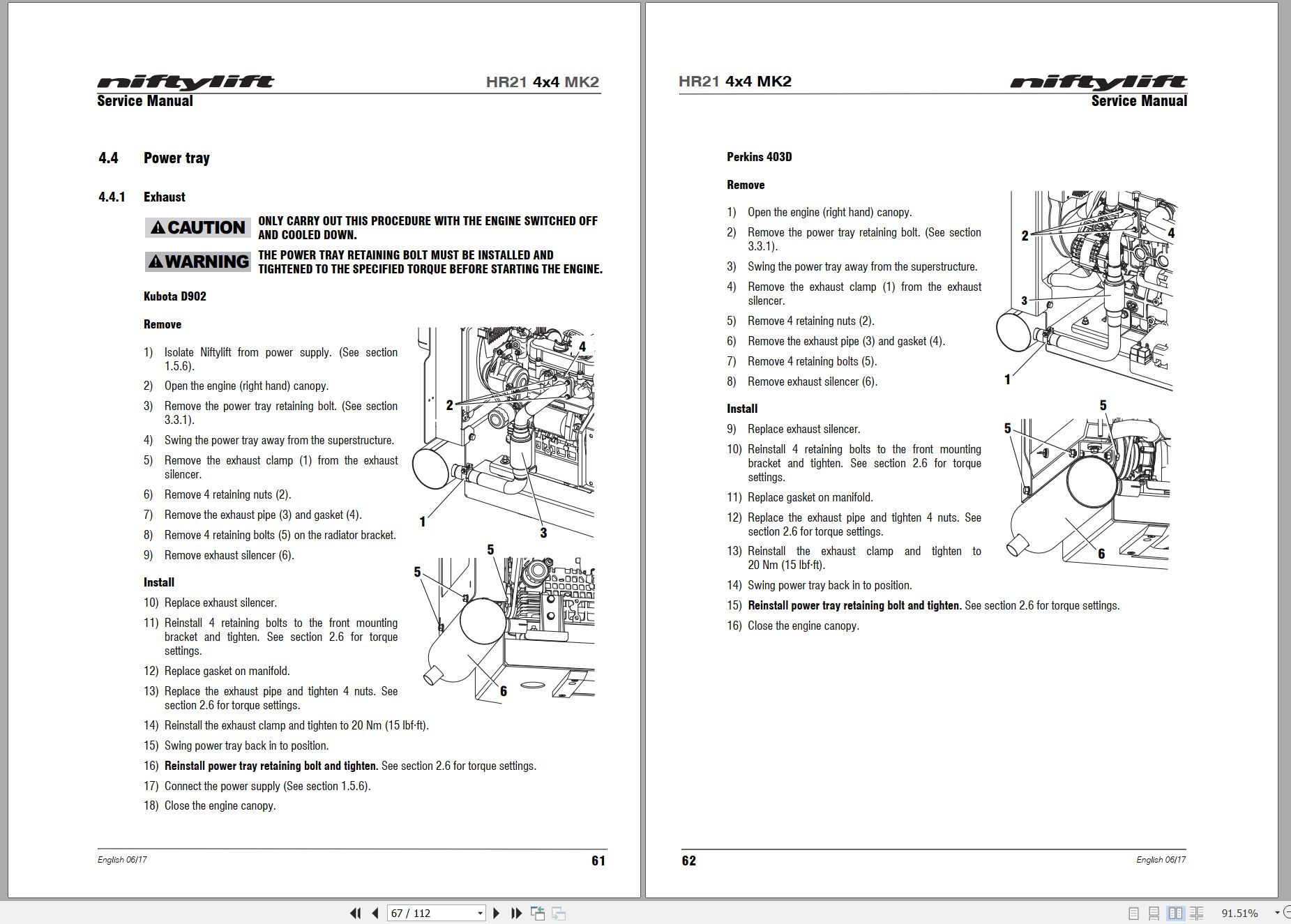
4.4 Power tray
4.4.1 Exhaust
4.4.2 Fan belt
4.5 Base assembly
4.5.1 Steer cylinder
4.6 Superstructure
4.6.1 Tilt sensor
4.6.2 Sensor calibration
5 System overview
5.1 Introduction
5.1.1 Hybrid system
5.1.2 Hybrid terminology
5.1.3 Battery states
5.1.4 Power modes
5.1.5 Operation
5.2 Diesel system
5.3 Boom system
5.3.1 Boom switch
5.3.2 Telescopic boom switch
5.3.3 Boom enable valve
5.4 Drive system
5.4.1 Hybrid & diesel
5.5 Charging system and batteries
5.5.1 Charging system – diesel
5.5.2 Charging system – hybrid
5.5.3 Absorbent Glass Mat (AGM) batteries
5.5.4 Lithium (Li-ion) batteries
5.6 Hydraulic system overview
5.7 Load sensing pump
5.8 Drive control valve
5.9 Four wheel drive (4×4)
5.10 Brake release
5.11 Steering
5.12 Suspension
5.13 Electrical control system overview
5.14 Control logic
5.16 Motor controller
5.17 Niftylift diagnostics
6 Troubleshooting guide
6.1 Troubleshooting information
6.2 Platform function fault finding
6.3 Engine fault finding
6.4 Engine fault codes
6.5 Gearbox fault finding
6.6 Error codes
6.6.1 Error cause (1st byte)
6.6.2 Error source (2nd byte)
6.6.3 Safety controller
6.6.4 Application specific error code (3rd byte)
6.6.5 Application specific (motor controller) error code (3rd byte)
6.6.6 Error class (4th byte)
Blank Page
12_MANUAL CHANGE NOTICE, HR21 4X4 MK2 PARTS M51047 (issue 001) 45420.pdf (2 Pages)
Related Products
-
NIFTYLIFT Towable Boom Lifts TM50 57219 Operating Service Parts Manual And Diagram 2025
50 USDSize: 27.83 MBFormat: PDFLanguage: EnglishBrand: NIFTYLIFTType of Machine: Towable Boom LiftsType of Manual: Service Manual, Operating Manual, Parts Manual, Electrical Schematic, Hydraulic Schematic,Model: NIFTYLIFT TM50 Towable Boom LiftsSerial Number: 57219Publication Date: 2025
REALEASE :
REALEASE :
-
NIFTYLIFT Towable Boom Lifts TM50 56687 Operating Service Parts Manual And Diagram 2025
50 USDSize: 20.05 MBFormat: PDFLanguage: EnglishBrand: NIFTYLIFTType of Machine: Towable Boom LiftsType of Manual: Service Manual, Operating Manual, Parts Manual, Electrical Schematic, Hydraulic Schematic,Model: NIFTYLIFT TM50 Towable Boom LiftsSerial Number: 56687Publication Date: 2025
REALEASE :
REALEASE :
-
NIFTYLIFT Towable Boom Lifts TM64 55060 Operating Service Parts Manual And Diagram 2023
40 USDSize: 28.83 MBFormat: PDFLanguage: EnglishBrand: NIFTYLIFTType of Machine: Towable Boom LiftsType of Manual: Service Manual, Operating Manual, Parts Manual, Electrical Schematic, Hydraulic Schematic,Model: NIFTYLIFT TM64 Towable Boom LiftsSerial Number: 55060Publication Date: 2023
REALEASE :
REALEASE :
-
NIFTYLIFT Towable Boom Lifts TM64 56064 Operating Service Parts Manual And Diagram 2023
40 USDSize: 28.80 MBFormat: PDFLanguage: EnglishBrand: NIFTYLIFTType of Machine: Towable Boom LiftsType of Manual: Service Manual, Operating Manual, Inspection Manual, Parts Manual, Electrical Schematic, Hydraulic Schematic,Model: NIFTYLIFT TM64 Towable Boom LiftsSerial Number: 56064Publication Date: 2023
REALEASE :
REALEASE :
-
NIFTYLIFT Towable Boom Lifts TM64 52414 Operating Service Parts Manual And Diagram 2022
40 USDSize: 29.17 MBFormat: PDFLanguage: EnglishBrand: NIFTYLIFTType of Machine: Towable Boom LiftsType of Manual: Service Manual, Operating Manual, Parts Manual, Electrical Schematic, Hydraulic Schematic,Model: NIFTYLIFT TM64 Towable Boom LiftsSerial Number: 52414Publication Date: 2022
REALEASE :
REALEASE :
-
NIFTYLIFT Towable Boom Lifts TM50 56720 Operating Service Parts Manual And Diagram 2025
50 USDSize: 27.98 MBFormat: PDFLanguage: EnglishBrand: NIFTYLIFTType of Machine: Towable Boom LiftsType of Manual: Service Manual, Operating Manual, Parts Manual, Electrical Schematic, Hydraulic Schematic,Model: NIFTYLIFT TM50 Towable Boom LiftsSerial Number: 56720Publication Date: 2025
REALEASE :
REALEASE :
-
NIFTYLIFT Towable Boom Lifts TM50 58728 Operating Service Parts Manual And Diagram 2025
50 USDSize: 20.05 MBFormat: PDFLanguage: EnglishBrand: NIFTYLIFTType of Machine: Towable Boom LiftsType of Manual: Service Manual, Operating Manual, Parts Manual, Electrical Schematic, Hydraulic Schematic,Model: NIFTYLIFT TM50 Towable Boom LiftsSerial Number: 58728Publication Date: 2025
REALEASE :
REALEASE :
-
NIFTYLIFT Towable Boom Lifts TM64 55045 Operators Service Manual Diagram 2023
40 USDSize: 28.66 MBFormat: PDFLanguage: EnglishBrand: NIFTYLIFTType of Machine: Towable Boom LiftsType of Manual: Service Manual, Operating Manual, Parts Manual, Electrical SchematicModel: NIFTYLIFT TM64 Towable Boom LiftsSerial Number: 55045Publication Date: 2023
REALEASE :
REALEASE :