
9 ITEMSVIEW CART


Total: 750.00
Expert Support
Full Speed
100% Working
40 USD
List of Files:
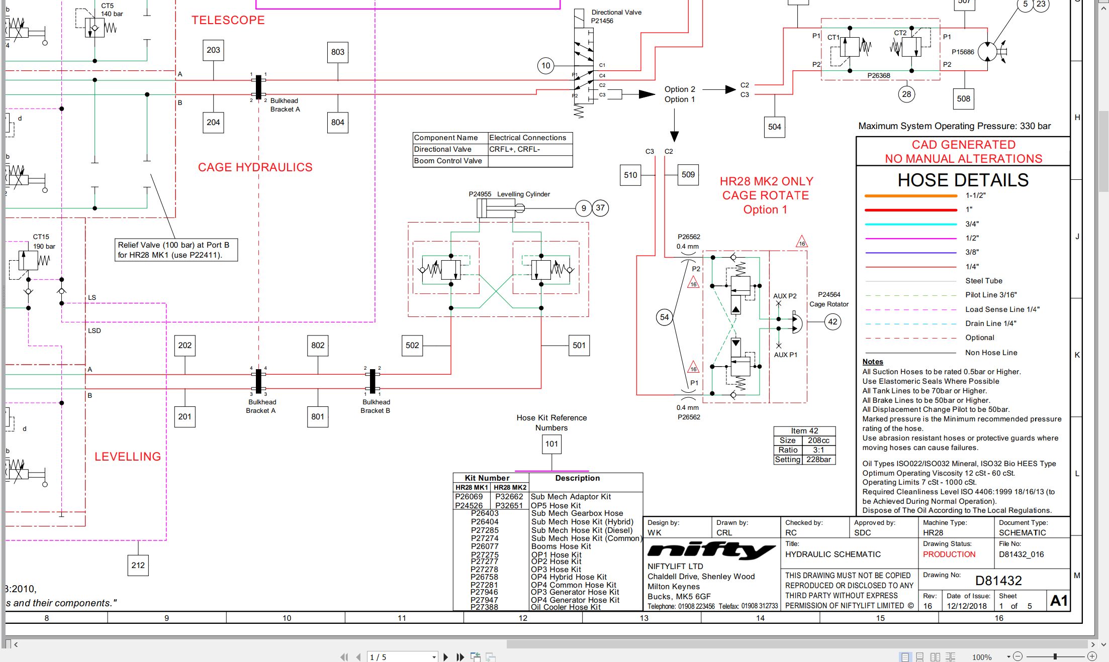
01_HYDRAULIC SCHEMATIC – HR28 D81432 (issue 016) 41731.pdf (5 Pages)
Contents:
D81432_016
Schematics
D81432_Sht1
D81432_Sht2
D81432_Sht3
BOMS
D81432_Sht4
D81432_Sht5
02_STOWED DIMENSIONS, HR28 MK2 D81639 (issue 002) 41731.pdf (1 Pages)
03_LIFTING POINTS, HR28 MK2 D81742 (issue 001) 41731.pdf (2 Pages)
04_TRANSPORT & TIE DOWN, HR28 MK2 D81748 (issue 001) 41731.pdf (1 Pages)
05_TURNING CIRCLE, HR28 MK2 D81753 (issue 001) 41731.pdf (1 Pages)
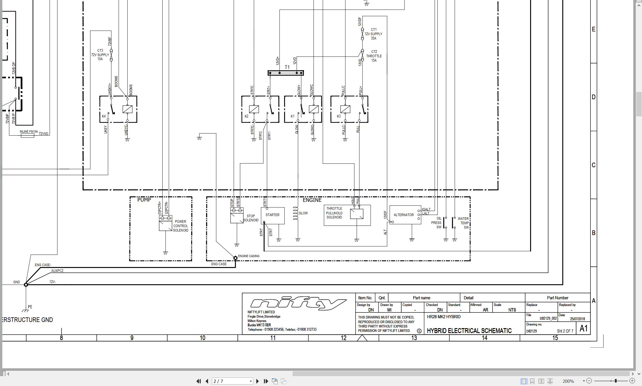
06_ELECTRICAL SCHEMATIC HR28 MK2 HYBRID D82129 (issue 002) 41731.pdf (7 Pages)
07_WORKING ENVELOPE, HR28 4×4 MK2 D82134 (issue 001) 41731.pdf (1 Pages)
08_HR28 (SP85) PARTS MANUAL M50440 (issue 006) 41731.pdf (96 Pages)
Contents:
chassis assembly
1.1 base assembly
1.2 axle assembly (front)
1.3 suspension valve block
superstructure
2.1 superstructure assembly – (control side)
2.2 superstructure assembly – (engine side)
2.3 Diesel engine
2.4 Base control assembly
2.5 Engine box assembly
2.6 Charger inlet assembly
2.7 Generator assembly (Option)
2.8 Voltage control box (Generator)
2.9 Track unit (Niftylink)
boom assemblies
3.1 links assembly
3.2 telescope assembly (part 1)
3.3 telescope assembly (part 2)
3.4 Lift/Luffing cylinder
3.5 Levelling cylinder
3.6 Energy chain
cage and flyboom
4.1 cage assembly
4.2 cage console assembly
4.3 SiOPS assembly
4.4 cage rotate assembly
4.5 flyboom assembly
4.6 flyboom cylinder
4.7 control panel assembly
labelling
5.1 Label locations
Figure 5.1
Labels 1 to 32
Labels 33 to 50
09_HR28 4×4 MK2 SERVICE MANUAL UK AUS M50670 (issue 001) 41731.pdf (103 Pages)
Contents:
1 Introduction and general information
1.1 Foreword
1.1.1 Defined maintenance terms
1.2 Warranty
1.3 Scope
1.4 General maintenance information
1.4.1 Pre-maintenance checks
1.4.2 Maintenance information
1.4.3 Frequent inspection
1.4.4 Annual inspection
1.5 Maintenance safety information
1.5.1 Personal injury prevention
1.5.2 Machine damage prevention
1.5.3 Diesel system safety
1.5.4 Electrical safety
1.5.5 Hydraulic safety
1.5.6 Environmental awareness
2 Specifications
2.1 Engine specifications
2.2 Gearbox specifications
2.3 Function times
2.4 Fluid properties
2.4.1 Fluid volumes
2.4.2 Engine oil specifications
2.4.3 Gearbox oil specifications
2.4.4 Hydraulic oil specifications
2.4.5 Engine coolant specifications
2.4.6 Hydraulic pressure settings
2.5 Tyre specifications
2.6 Torque settings
2.7 Hydraulic hose and fitting torque specifications
3 Preventative maintenance
3.1 Maintenance schedules
3.1.1 Engine maintenance
3.1.2 Machine maintenance
3.2 Consumables
3.2.1 Data, safety and specification
3.3 Power tray
3.3.1 Engine oil level check (daily)
3.3.2 Engine oil replace
3.3.3 Engine oil filter replace
3.3.4 Engine coolant level check (daily)
3.3.5 Coolant replace
3.3.6 Coolant hoses and clamp bands check
3.3.7 Antifreeze check
3.3.8 Coolant hoses and clamp bands check
3.3.9 Air filter element maintenance
3.3.10 Fuel pipes check
3.3.11 Fuel filter replace
3.3.12 Bleeding air from the fuel system
3.3.13 Exhaust system inspect
3.3.14 Fan belt check – every 100 hours
3.4 Drive hub gearbox
3.4.1 Oil replace
3.4.2 Bleeding air from the braking circuit
3.5 Batteries
3.5.1 Condition check (daily)
3.5.2 Storage
3.5.3 Batteries (DC system)
3.6 Inverter / generator and power to cage options
3.6.1 Condition check (daily)
3.7 Hydraulic oil
3.7.1 Level check (weekly)
3.7.2 Return filter check (monthly)
3.7.3 Pressure filter check (weekly)
3.7.4 Hydraulic oil and filters replace
3.8 Telescopic boom
3.8.1 Wear pad check (monthly)
3.8.2 Hose trunking and energy chain check (weekly)
3.8.3 Boom pivot pin check (daily)
3.8.4 Lubricate boom pivot bushes (annually)
3.8.5 Boom wire rope check (every 6 months)
3.9 Boom rotation gear
3.9.1 Slew gear engagement check (monthly)
3.9.2 Lubricate Slew ring (monthly)
3.9.3 Slew ring bolts check (annually)
3.10 Chassis
3.10.1 Earth strap check (daily)
3.11 Cage rotator
3.11.1 Cage rotator check (monthly)
4 Repair procedures
4.1 General
4.1.1 Fuses
4.2 Platform/Cage
4.2.1 Footswitch – contact switch replace
4.3 Booms
4.3.1 Energy chain link
4.4 Power tray
4.4.1 Exhaust
4.4.2 Fan belt
4.5 Base assembly
4.5.1 Steer cylinders
4.6 Superstructure
4.6.1 Tilt sensor
4.6.2 Sensor calibration
5 System overview
5.1 Introduction
5.1.1 Hybrid system
5.2 Hybrid operation
5.3 Boom system
5.3.1 Boom switch
5.3.2 Telescopic boom switch
5.4 Drive system
5.4.1 Hybrid
5.5 Charging system and batteries
5.5.1 Charging system
5.5.2 Charging system – diesel engine
5.5.3 Battery charging – extension leads
5.6 Hydraulic system overview
5.7 Load sensing pump
5.8 Hydraulic valve blocks
5.9 Diff lock
5.10 Brake release
5.11 Steering
5.11.1 Steer valve
5.12 Boom operation
5.12.1 Boom control valve
5.13 Electrical control system overview
5.14 Control logic
5.15 Motor generator
5.16 Motor control
6 Troubleshooting guide
6.1 Trouble shooting information
6.2 Platform function fault finding
6.3 Engine fault finding
6.4 Gearbox fault finding
6.5 Error codes
6.5.1 Safety control devices
6.5.2 Error codes (safety control devices)
6.5.3 Application specific
6.5.4 Application specific error codes (general)
6.5.5 Application specific error codes (motor controller)
6.5.6 Inverter error codes
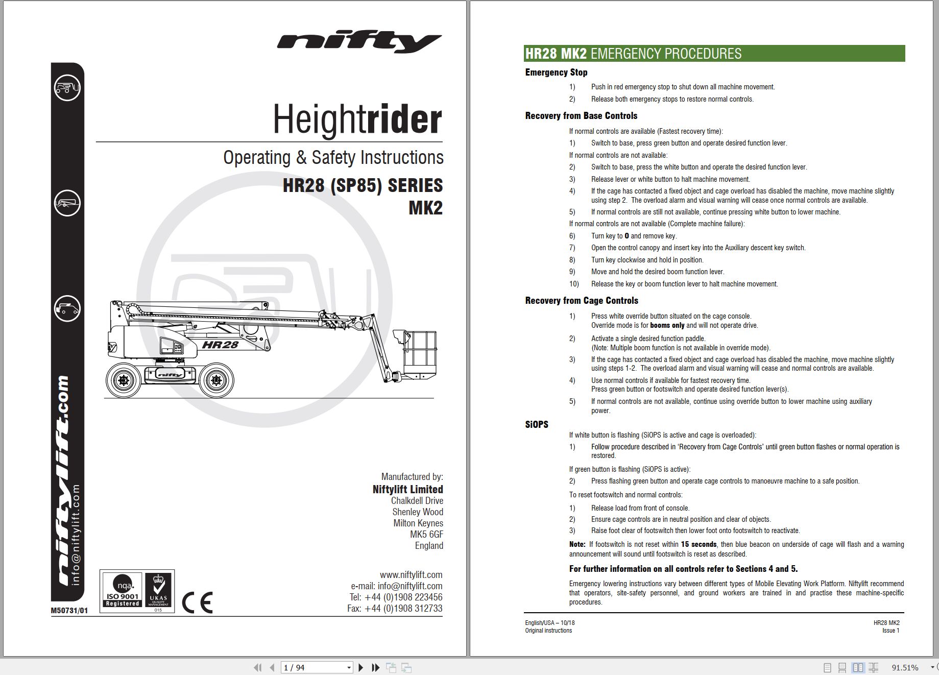
10_HR28 HYBRID MK2 OPERATING MANUAL UK M50731 (issue 001) 41731.pdf (94 Pages)
Contents:
1 Introduction and General Information
1.1 FOREWORD
1.2 SCOPE
1.3 INTRODUCING THE HEIGHT RIDER SELF-PROPELLED (SP) SERIES
1.4 GENERAL SPECIFICATION
1.5 IDENTIFICATION (UK PLATE)
1.6 EC DECLARATION OF CONFORMITY (Typical)
2 Safety
2.1 MANDATORY PRECAUTIONS
2.2 ENVIRONMENTAL LIMITATIONS
2.3 NOISE AND VIBRATION
2.4 TEST REPORT
3 Preparation and Inspection
3.1 UNPACKING
3.2 PREPARATION FOR USE
3.3 PRE-OPERATIONAL SAFETY CHECK SCHEDULES
3.3.1 DAILY SAFETY CHECKS
3.3.2 WEEKLY SAFETY CHECKS
3.3.3 MONTHLY SAFETY CHECKS
3.3.4 BI-ANNUAL SAFETY CHECKS
3.3.5 ANNUAL SAFETY CHECKS
3.4 PLACARD, DECALS & INSTALLATION (UK SPEC)
3.5 TORQUE REQUIREMENTS
4 Operation
4.1 CONTROL CIRCUIT COMPONENTS
4.1.1 GROUND CONTROLS
4.1.2 PLATFORM
4.1.3 FUSES
4.2 GROUND CONTROL OPERATION
4.2.1 GROUND CONTROL FUNCTIONS
4.2.2 OPERATION
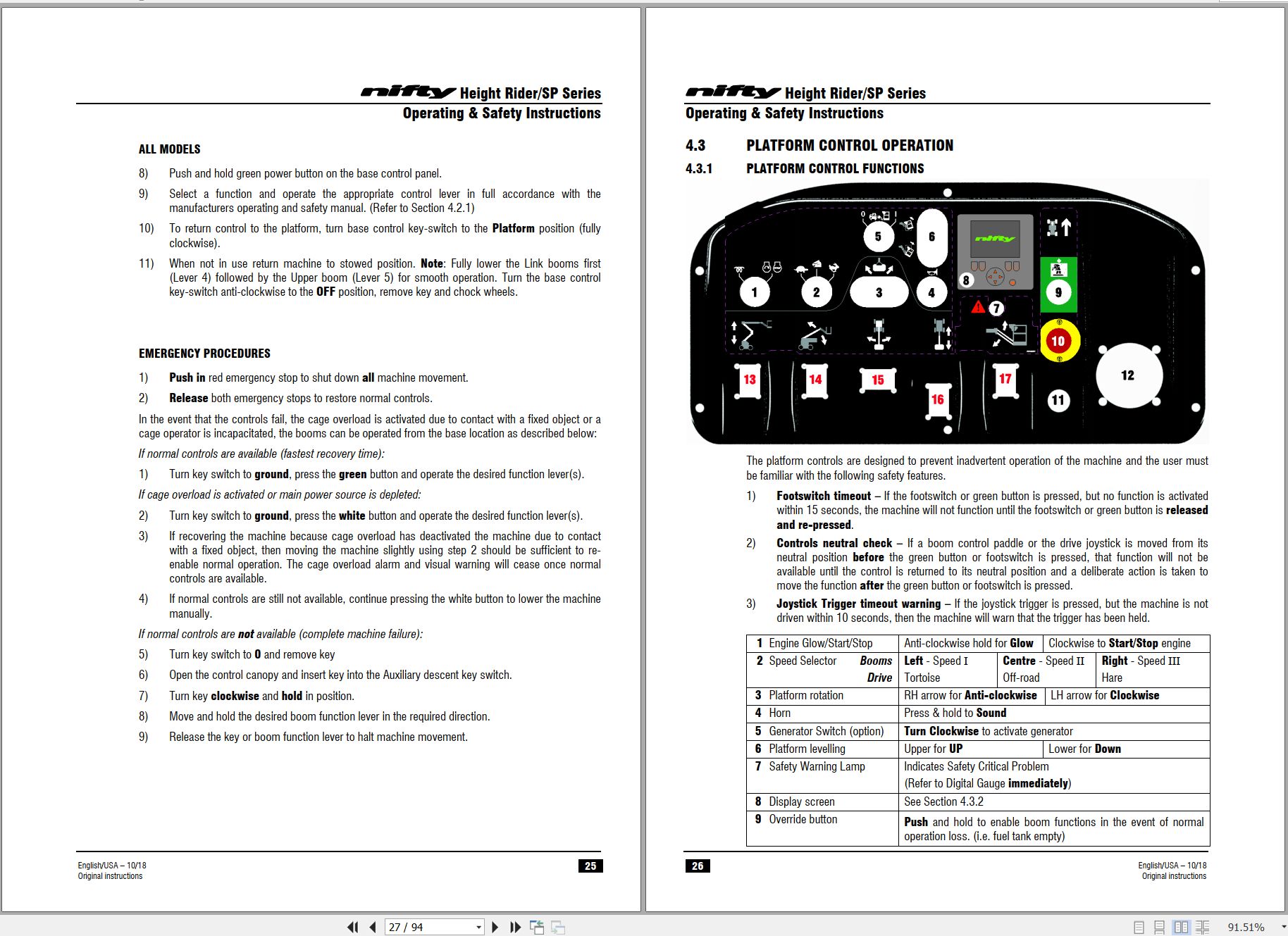
4.3 PLATFORM CONTROL OPERATION
4.3.1 PLATFORM CONTROL FUNCTIONS
4.3.2 DISPLAY SCREEN
4.3.3 INFORMATION ICONS
4.3.4 MENU SCREENS
4.3.5 OPERATION
4.3.6 SiOPSTM – LOAD SENSING CONSOLE
4.4 DRIVING CONTROLS
4.5 CAGE WEIGH SYSTEM
4.5.1 LOAD CELL VERSION
4.5.2 CALIBRATION, INSPECTION AND MAINTENANCE
4.6 BATTERIES AND CHARGING
4.7 TRANSPORTING, TOWING, CRANEAGE, STORAGE AND SETTING TO WORK
4.7.1 TRANSPORTING
4.7.2 CAGE STOWING
4.7.3 TOWING
4.7.4 CRANEAGE
4.7.5 STORAGE
4.7.6 SETTING TO WORK
5 Emergency Controls
5.1 GENERAL
5.2 IN THE EVENT OF AN INCAPACITATED OPERATOR
5.3 IN THE EVENT OF MACHINE FAILURE
5.4 INCIDENT NOTIFICATION
6 Responsibilities
6.1 CHANGES IN OWNERSHIP
6.2 MANUAL OF RESPONSIBILITIES (USA only)
6.3 INSPECTION/SERVICE/PRE-HIRE CHECK LIST
Appendix A
Appendix B
11_HR28 WIRE ROPE INSPECTION MANUAL UK M50752 (issue 002) 41731.pdf (11 Pages)

REALEASE :
REALEASE :

REALEASE :
REALEASE :

REALEASE :
REALEASE :

REALEASE :
REALEASE :

REALEASE :
REALEASE :

REALEASE :
REALEASE :

REALEASE :
REALEASE :

REALEASE :
REALEASE :
 Automotive - Heavy Equipment - Truck & Bus - Forklift - Crane