
3 ITEMSVIEW CART


Total: 65.00
Expert Support
Full Speed
100% Working
50 USD
List of Files:
01_210 SD ELECTRICAL FAMILY TREE D81250 (issue 006) 57783.pdf (1 Pages)
02_LIFTING POINTS, SD210 D81338 (issue 004) 57783.pdf (2 Pages)
Contents:
Sheets and Views
D81338_004-Sheet 1
D81338_004-Sheet 2
03_WORKING ENVELOPE, SD210 4x4x4 D81651 (issue 003) 57783.pdf (2 Pages)
Contents:
Sheets and Views
D81651_003-Sheet 1 – Metric
D81651_003-Sheet 2 – Imperial
04_TURNING CIRCLE, SD210 D81736 (issue 002) 57783.pdf (1 Pages)
05_STOWED DIMENSIONS, SD210 4x4x4 D81940 (issue 003) 57783.pdf (1 Pages)
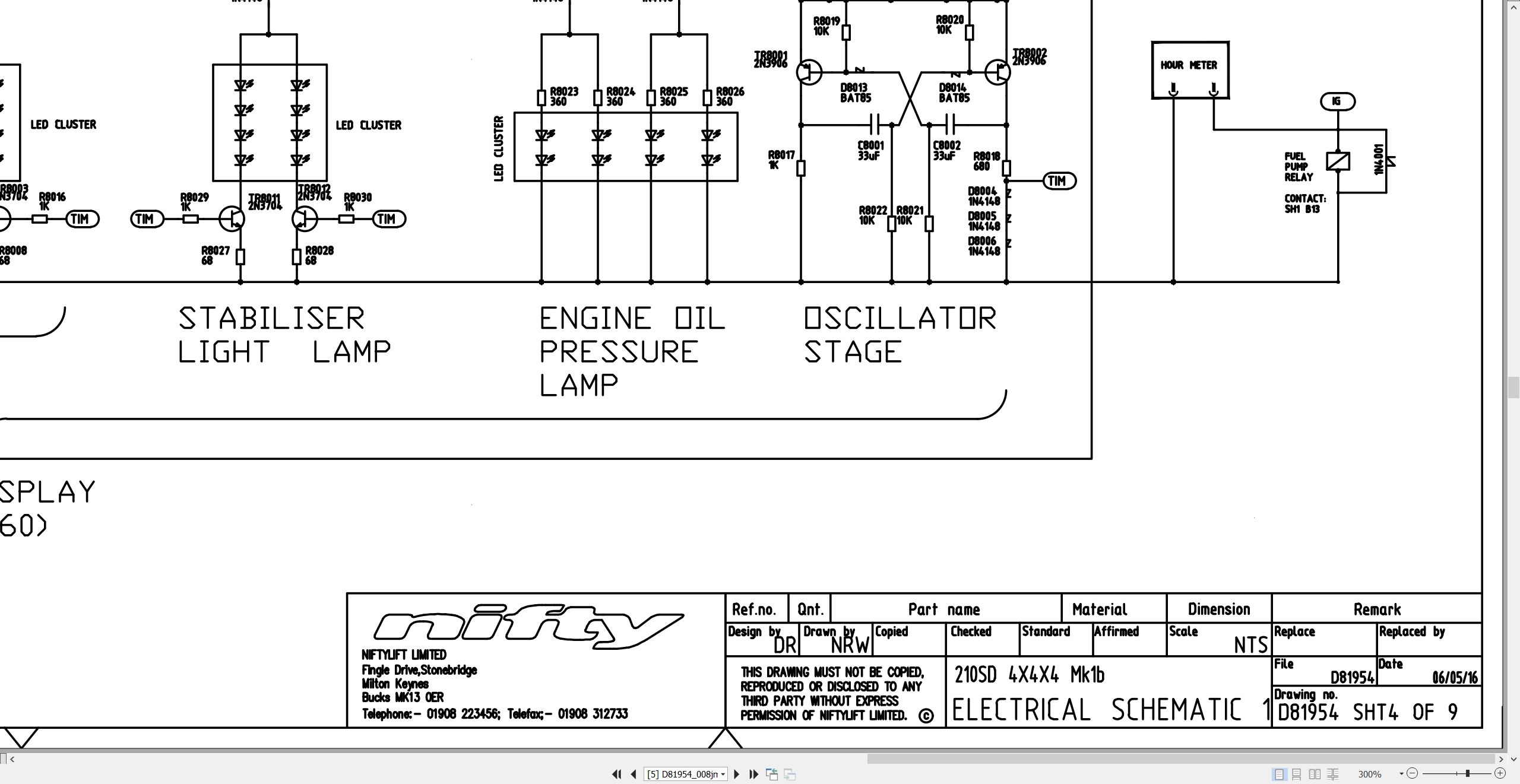
06_ELECTRICAL SCHEMATICS – SD210 MK1B D81954 (issue 008) 57783.pdf (10 Pages)
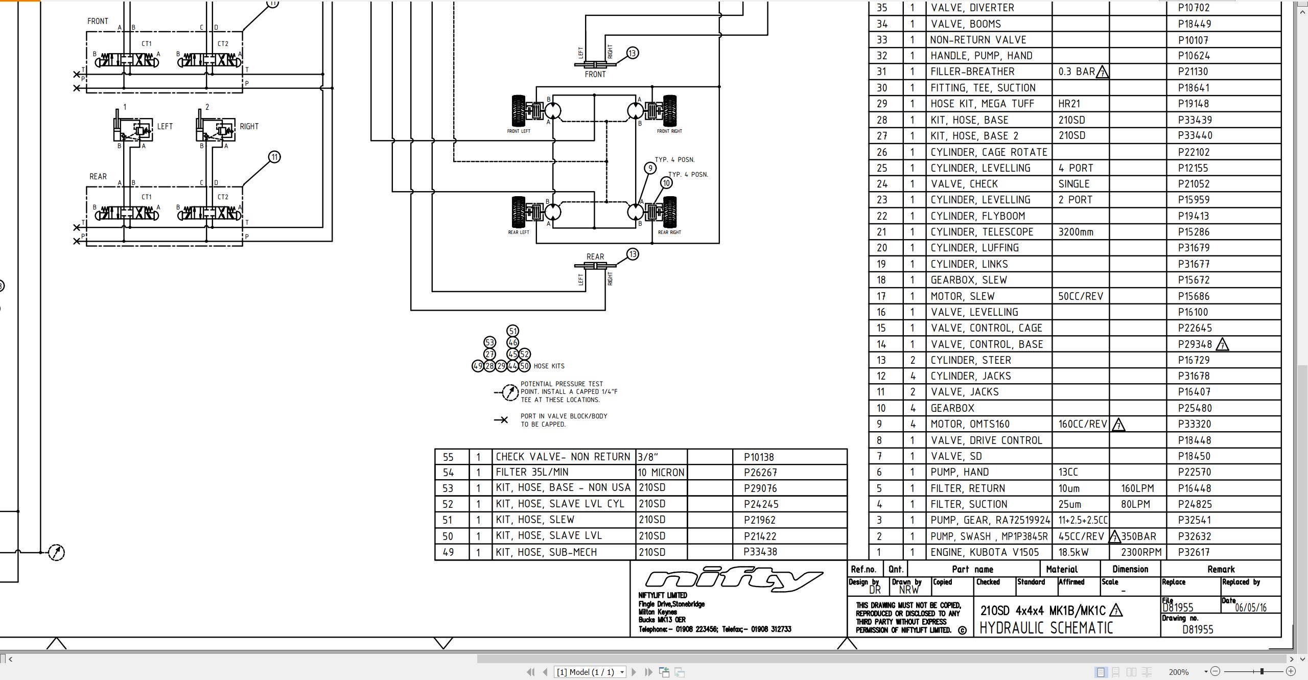
07_HYDRAULIC SCHEMATICS – SD210 MK1B D81955 (issue 007) 57783.pdf (1 Pages)
Contents:
Sheets and Views
Model
08_210SD SD64 PARTS MANUAL M50180 (issue 016) 57783.pdf (98 Pages)
Contents:
Parts Order Form
Contents
chassis assembly
1.1 Base assembly
1.2 Axle assembly
1.3 Stabiliser assembly
superstructure
2.1 Superstructure assembly
2.2 Power tray assembly
2.3 Diesel engine – Part 1
2.4 Diesel engine – Part 2
2.5 Control valve (6 spool)
2.6 Base control box
2.7 PCB control box
2.8 Safety box assembly
2.9 Main Valve block
2.10 Drive Control Valve block
2.11 Booms Valve block
boom assemblies
3.1 Links assembly
3.2 Telescope assembly (Part 1)
3.3 Telescope assembly (Part 2)
3.4 Lift & Luffing cylinder
3.5 Levelling cylinders
3.6 Levelling valve
3.7 Energy chain
cage and flyboom
4.1 Cage assembly
4.2 cage console assembly
4.3 SiOPS assembly
4.4 cage rotate assembly
4.5 flyboom assembly
4.6 Flyboom cylinder
4.7 Control panel assembly
4.8 Control valve (6 spool)
labelling
5.1 Label locations
Figure 5.1
Labels 1 to 37
Labels 38 to 55
09_CHAIN INSPECTION MANUAL UK USA M50280 (issue 003) 57783.pdf (43 Pages)
Contents:
1 Periodic Inspection
1.1 Elongation
1.1.1 Elongation check using Chain wear gauge
1.1.2 After-use care of the Chain wear gauge
1.2 Edge wear
1.3 Turning or protruding pins
1.4 Cracked plates
1.4.1 Fatigue cracking
1.4.2 Stress corrosion cracking
1.4.3 Corrosion fatigue
1.5 Other modes of failure
1.5.1 Ultimate strength failure
1.5.2 Tight joints
1.6 Addenda
1.6.1 AL444 leaf chain
2 Lubrication
2.1 Recommended lubricants
2.2 Lubricant application
3 Inner chain inspection
3.1 Removing inner chain for inspection
3.2 Applying load to removed chain to take up clearance
3.2.1 Manufacturing Bracket, chain securing
4 Chain slack/sag
4.1 Tensioning using Chain tension gauge T00267
5 Installation
5.1 Chain movement
5.2 Lubrication
5.3 Paint
5.4 Protection
5.5 Chain mountings
5.6 Pulleys
6 Chain inspection tools
6.1 Chain inspection tools order form
10_Kubota V1505 Operators Manual M50292 (issue 001) 57783 16622-8916-8.pdf (38 Pages)
11_SD64 4x4x4 SERVICE MANUAL USA M50810 (issue 003) 57783.pdf (66 Pages)
Contents:
1 Introduction and general information
1.1 Foreword
1.1.1 Defined maintenance terms
1.2 Warranty
1.3 Scope
1.4 General maintenance information
1.4.1 Pre-maintenance checks
1.4.2 Maintenance information
1.4.3 Frequent inspection
1.4.4 Annual inspection
1.5 Maintenance safety information
1.5.1 Personal injury prevention
1.5.2 Machine damage prevention
1.5.3 Diesel system safety
1.5.4 Hydraulic safety
1.5.5 Electrical safety
1.5.6 Environmental awareness
2 Specifications
2.1 Engine specifications
2.2 Gearbox specifications
2.3 Function times
2.4 Fluid properties
2.4.1 Fluid volumes
2.4.2 Engine oil specifications
2.4.3 Gearbox oil specifications
2.4.4 Hydraulic oil specifications
2.4.5 Engine coolant specifications
2.4.6 Hydraulic pressure settings
2.5 Tire specifications
2.6 Torque settings
2.7 Hydraulic hose and fitting torque specifications
3 Preventative maintenance
3.1 Maintenance schedules
3.1.1 Engine maintenance
3.1.2 Machine maintenance
3.2 Consumables
3.2.1 Data, safety and specification
3.3 Engine
3.3.1 Power tray
3.3.2 Engine oil level check
3.3.3 Engine oil replace
3.3.4 Engine oil filter replace
3.3.5 Engine coolant level check
3.3.6 Engine coolant replace
3.3.7 Coolant hoses and clamp bands check
3.3.8 Antifreeze check
3.3.9 Air filter element maintenance
3.3.10 Fuel pipes check
3.3.11 Fuel filter replace
3.3.12 In-line fuel filter replace
3.3.13 Exhaust system inspect
3.3.14 Fan belt check
3.4 Base assembly
3.4.1 Tire condition check
3.4.2 Tire pressure check
3.4.3 Track rod end lubrication (daily)
3.5 Drive hub gearbox
3.5.1 Oil replace
3.5.2 Bleeding air from the braking circuit
3.6 Batteries
3.6.1 Condition check (daily)
3.7 Hydraulic oil
3.7.1 Level check (weekly)
3.7.2 Suction & return filter check (monthly)
3.7.3 Pressure filter check (weekly)
3.7.4 Hydraulic oil and filters replace
3.8 Telescopic boom
3.8.1 Wear pad check (monthly)
3.8.2 Hose trunking and energy chain check (weekly)
3.8.3 Boom pivot pin check (daily)
3.8.4 Boom pivot bushes lubricate (yearly)
3.8.5 Chain inspection
3.9 Boom rotation gear
3.9.1 Rotation gear engagement check (monthly)
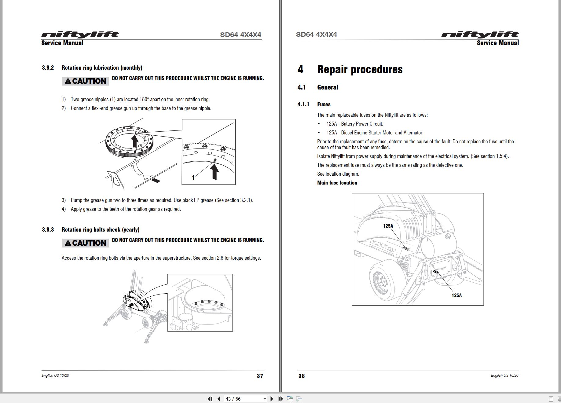
3.9.2 Rotation ring lubrication (monthly)
3.9.3 Rotation ring bolts check (yearly)
4 Repair procedures
4.1 General
4.1.1 Fuses
4.2 Platform/basket
4.2.1 Footswitch – contact switch replace
4.3 Booms
4.3.1 Energy chain link
4.4 Power tray
4.4.1 Exhaust
4.4.2 Fan belt
4.4.3 Throttle solenoid
4.5 Base assembly
4.5.1 Steer cylinders
4.5.2 Shock absorber
4.5.3 Stabilizer microswitch
5 System Overview
5.1 Power system
5.2 Boom system
5.2.1 Booms valve
5.2.2 Boom switches
5.3 Drive system
5.3.1 Overview
5.3.2 Charging system
5.4 Hydraulic system overview
5.5 Hydraulic pumps
5.6 Hydraulic valve blocks
5.7 Brake release
5.8 Steering
5.9 Electrical control system overview
5.10 Control logic
6 Troubleshooting guide
6.1 Troubleshooting information
6.2 Platform function fault finding
6.3 Engine fault finding
6.4 Gearbox fault finding
Blank Page
12_SD64 OPERATING MANUAL M50907 (issue 002) 57783.pdf (45 Pages)
Contents:
1 Introduction and General Information
1.1 FOREWORD
1.2 SCOPE
1.3 INTRODUCING THE NIFTYLIFT SELF-DRIVE (SD) SERIES
1.4 GENERAL SPECIFICATION
1.5 IDENTIFICATION (USA PLATE)
2 Safety
2.1 MANDATORY PRECAUTIONS
2.2 ENVIRONMENTAL LIMITATIONS
2.3 NOISE AND VIBRATION
2.4 TEST REPORT
2.5 ELECTRICAL SAFETY
3 Preparation and Inspection
3.1 UNPACKING
1) Remove all ropes, straps and or chains used to secure the aerial basket during transit.
2) Ensure any ramp, loading dock or forklift used is capable of supporting or lifting the aerial basket.
3) If the Niftylift is to be driven off, please ensure that the operator has read and fully understood this entire manual. Refer to the appropriate section for precise operating instructions.
3.2 PREPARATION FOR USE
3.3 PRE-OPERATIONAL SAFETY CHECK SCHEDULES
3.3.1 DAILY SAFETY CHECKS
3.3.2 WEEKLY SAFETY CHECKS
3.3.3 MONTHLY SAFETY CHECKS
3.3.4 ANNUAL SAFETY CHECKS
3.4 PLACARD, DECALS & INSTALLATION
3.5 TORQUE REQUIREMENTS
4 Operation
4.1 CONTROL CIRCUIT COMPONENTS
4.2 SETTING UP PROCEDURES
4.3 GROUND CONTROL OPERATION
4.3.1 GROUND CONTROL INSTRUCTIONS
4.4 BASKET CONTROL OPERATION
4.4.1 BASKET CONTROL INSTRUCTIONS
4.4.2 SiOPSTM – LOAD SENSING CONSOLE (If fitted)
4.5 DRIVING CONTROLS
1) Using the electric luffing switch on the basket console, elevate the basket to the drive position for better visibility. This elevates the basket approximately 1m above the ground.
2) Check proposed route for possible hazards, obstructions and personnel.
3) Depress switch located on the front of the joystick.
4) Use the Drive Speed selectors on the basket control station to determine speed.
5) Select drive joystick located on the basket console.
4.6 OUTRIGGERS
4.7 BASKET WEIGH SYSTEM (Optional)
4.7.1 LOAD CELL VERSION
4.7.2 FUNCTION
4.7.3 CALIBRATION, INSPECTION AND MAINTENANCE
4.8 TRANSPORTING, TOWING, CRANEAGE, STORAGE AND SETTING TO WORK
4.8.1 TRANSPORTING
4.8.2 TOWING
4.8.3 CRANEAGE
4.8.4 STORAGE
4.8.5 SETTING TO WORK
5 Emergency Controls
5.1 GENERAL
5.2 IN THE EVENT OF AN INCAPACITATED OPERATOR
5.3 IN THE EVENT OF MACHINE FAILURE
5.3.1 BOOM OVERRIDE
5.3.2 FRONT STEER OVERRIDE
5.4 TOWING
5.4.1 IDENTIFYING GEARBOX TYPE
5.4.2 GEARBOX DISENGAGEMENT (TYPE 1)
5.4.3 GEARBOX DISENGAGEMENT (TYPE 2)
5.4.4 BRAKE RELEASE FOR TOWING
5.4.5 MANUAL OUTRIGGER RECOVERY
5.5 INCIDENT NOTIFICATION
6 Responsibilities
6.1 CHANGES IN OWNERSHIP
6.2 MANUAL OF RESPONSIBILITIES
6.3 INSPECTION/SERVICE/PRE-HIRE CHECK LIST
Blank Page

REALEASE :
REALEASE :

REALEASE :
REALEASE :

REALEASE :
REALEASE :

REALEASE :
REALEASE :

REALEASE :
REALEASE :

REALEASE :
REALEASE :

REALEASE :
REALEASE :

REALEASE :
REALEASE :
 Automotive - Heavy Equipment - Truck & Bus - Forklift - Crane