")

Expert Support
Full Speed
100% Working
NIFTYLIFT Articulating Boom Lifts SP64 55647 Operating Service Parts Manual And Diagram 2023
40 USD
- Description
Description
List of Files:
01_LIFTING POINTS, HR21 MK2 D81980 (issue 002) 55647.pdf (2 Pages)
Contents:
Sheets and Views
D81980_002-English
D81980_002-French
02_WORKING ENVELOPE, HR21 MK2 D81981 (issue 002) 55647.pdf (2 Pages)
Contents:
Sheets and Views
D81981_002-MEETERS
D81981_002-FEET
03_STOWED DIMENSIONS, HR21 MK2 D81982 (issue 002) 55647.pdf (2 Pages)
Contents:
Sheets and Views
D81982_002-Steel Cage
D81982_002-Tough Cage
04_TRANSPORT & TIE DOWN, HR21 MK D81983 (issue 001) 55647.pdf (1 Pages)
05_TURNING CIRCLE, HR21 MK2 D81984 (issue 002) 55647.pdf (1 Pages)
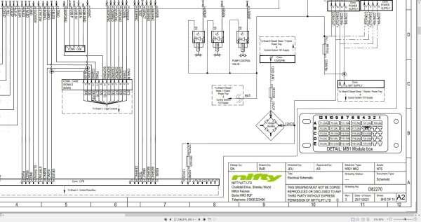
06_Electrical Schematic HR21 MK2 ANSI UPDAT D82270 (issue 003) 55647.pdf (14 Pages)
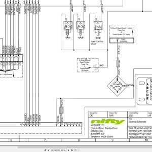
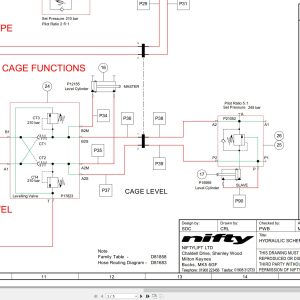
07_SCHEMATIC – HYDRAULIC HR21 4X4 MK2 D82900 (issue 010) 55647.pdf (5 Pages)
Contents:
D82900_010
Schematics
D82900_Sht1
D82900_Sht2
D82900_Sht3
BOMS
D82900_Sht4
D82900_Sht5
08_CHAIN INSPECTION MANUAL UK USA M50280 (issue 002) 55647.pdf (13 Pages)
Contents:
Blank Page
09_HR21 (SP64) MK2 PARTS MANUAL M50540 (issue 007) 55647.pdf (111 Pages)
Contents:
Front Cover
Parts Order Form
chassis assembly
1.1 base assembly
1.2 axle assembly (front)
1.3 axle assembly (rear)
1.4 hydraulic tray assembly
1.5 suspension valve block
1.6 generator assembly (option)
1.7 battery pod assembly – lithium (option)
1.8 battery charger assemblies
superstructure
2.1 Superstructure (1)
2.2 Superstructure (2)
2.3 Power tray assembly (Hybrid)
2.4 Power tray assembly (Diesel – Perkins)
2.5 Power tray assembly (Diesel – Kubota)
2.6 Diesel engine (Hybrid) – part 1
2.7 Diesel engine (Hybrid) – part 2
2.8 Diesel engine (Diesel – Perkins)
2.9 Diesel engine (Diesel – Kubota) – Part 1
2.10 Diesel engine (Diesel – Kubota) – Part 2
2.11 Base control assembly
2.12 Track unit (Niftylink)
boom assemblies
3.1 links assembly
3.2 telescope assembly (part 1)
3.3 telescope assembly (part 2)
3.4 lift & luffing cylinders
3.5 levelling cylinders
3.6 levelling valve assembly
3.7 energy chain
cage and flyboom
4.1 toughcage assembly
4.2 cage console assembly
4.3 SiOPS assembly
4.4 cage rotate assembly
4.5 flyboom assembly
4.6 flyboom cylinder
4.7 control panel assembly
labelling
5.1 Label locations
Figure 5.1
Labels 1 to 33
Labels 34 to 46
10_SP64 (HR21) MK2 SERVICE MANUAL USA M50649 (issue 002) 55647.pdf (110 Pages)
Contents:
1 Introduction and general information
1.1 Foreword
1.1.1 Defined maintenance terms
1.2 Warranty
1.3 Scope
1.4 General maintenance information
1.4.1 Pre-maintenance checks
1.4.2 Maintenance information
1.4.3 Frequent inspection
1.4.4 Annual inspection
1.5 Maintenance safety information
1.5.1 Personal injury prevention
1.5.2 Machine damage prevention
1.5.3 Diesel system safety
1.5.4 Hydraulic safety
1.5.5 Environmental awareness
1.5.6 Electrical safety
2 Specifications
2.1 Engine specifications
2.2 Gearbox specifications
2.3 Function times
2.4 Fluid properties
2.4.1 Fluid volumes
2.4.2 Engine oil specifications
2.4.3 Gearbox oil specifications
2.4.4 Hydraulic oil specifications
2.4.5 Engine coolant specifications
2.4.6 Hydraulic pressure settings
2.5 Tire specifications
2.6 Torque settings
2.7 Hydraulic hose and fitting torque specifications
3 Preventative maintenance
3.1 Maintenance schedules
3.1.1 Engine maintenance
3.1.2 Machine maintenance
3.2 Consumables
3.2.1 Data, safety and specification
3.3 Engine operations
3.3.1 Power tray
3.3.2 Engine oil level check (daily)
3.3.3 Engine oil replace
3.3.4 Engine oil filter replace
3.3.5 Engine coolant level check (daily)
3.3.6 Coolant replace
3.3.7 Antifreeze check
3.3.8 Coolant hoses and clamp bands check
3.3.9 Air filter element maintenance
3.3.10 In-line fuel filter replace
3.3.11 Fuel filter and water separator clean/replace
3.3.12 Fuel filter (cartridge type) replace
3.3.13 Bleeding air from the fuel system
3.3.14 Fuel pipes check
3.3.15 Exhaust system check
3.3.16 Fan belt check
3.4 Drive hub gearbox
3.4.1 Gearbox disengagement
3.4.2 Gearbox oil replace
3.4.3 Bleeding air from the braking circuit
3.5 Batteries
3.5.1 Condition check (daily)
3.5.2 Storage
3.6 Inverter / generator and power to basket options
3.6.1 Condition check (daily)
3.7 Hydraulic oil
3.7.1 Level check (weekly)
3.7.2 Return filter check (monthly)
3.7.3 Pressure filter check (weekly)
3.7.4 Hydraulic oil and filters replace
3.8 Telescopic boom
3.8.1 Wear pad check (monthly)
3.8.2 Hose trunking and energy chain check (weekly)
3.8.3 Lubricate boom pivot bushes (annually)
3.8.4 Boom pivot pin check (daily)
3.8.5 Boom chain inspection
3.9 Boom rotation gear
3.9.1 Rotation gear engagement check (monthly)
3.9.2 Lubricate rotation ring (monthly)
3.9.3 Rotation ring bolts check (annually)
3.10 Front axle
3.10.1 Lubricate steer pin (daily)
3.11 Chassis
3.11.1 Earth strap check (daily)
4 Repair procedures
4.1 General
4.1.1 Fuses
4.2 Platform/basket
4.2.1 Footswitch – contact switch replace
4.3 Booms
4.3.1 Energy chain link
4.4 Power tray
4.4.1 Exhaust
4.4.2 Fan belt
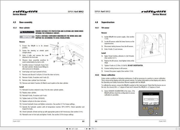
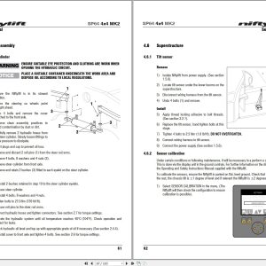
4.5 Base assembly
4.5.1 Steer cylinder
4.6 Superstructure
4.6.1 Tilt sensor
4.6.2 Sensor calibration
5 System overview
5.1 Introduction
5.1.1 Hybrid system
5.1.2 Hybrid terminology
5.1.3 Battery states
5.1.4 Power modes
5.1.5 Operation
5.2 Diesel system
5.3 Boom system
5.3.1 Boom switch
5.3.2 Telescopic boom switch
5.3.3 Boom enable valve
5.4 Drive system
5.4.1 Hybrid & diesel
5.5 Charging system and batteries
5.5.1 Charging system – diesel
5.5.2 Charging system – hybrid
5.5.3 Absorbent Glass Mat (AGM) batteries
5.5.4 Lithium (Li-ion) batteries
5.5.5 Battery charging – extension cords
5.6 Hydraulic system overview
5.7 Load sensing pump
5.8 Drive control valve
5.9 Four wheel drive (4×4)
5.10 Brake release
5.11 Steering
5.12 Suspension
5.13 Electrical control system overview
5.14 Control logic
5.16 Motor controller
5.17 Niftylift diagnostics
6 Troubleshooting guide
6.1 Troubleshooting information
6.2 Platform function fault finding
6.3 Engine fault finding
6.4 Engine ECM
6.5 Gearbox fault finding
6.6 Error codes
6.6.1 Error cause (1st byte)
6.6.2 Error source (2nd byte)
6.6.3 Safety controller
6.6.4 Application specific error code (3rd byte)
6.6.5 Application specific (motor controller) error code (3rd byte)
6.6.6 Error class (4th byte)
6.6.7 Inverter error codes
11_SP64 MK2 OPERATING MANUAL (USA) M50918 (issue 002) 55647.pdf (85 Pages)
Contents:
1 Introduction and General Information
1.1 FOREWORD
1.2 SCOPE
1.3 INTRODUCING THE HEIGHT RIDER SELF-PROPELLED (SP) SERIES
1.4 GENERAL SPECIFICATION
1.5 IDENTIFICATION (USA PLATE)
2 Safety
2.1 MANDATORY PRECAUTIONS
2.2 ENVIRONMENTAL LIMITATIONS
2.3 NOISE AND VIBRATION
2.4 TEST REPORT
2.5 ELECTRICAL SAFETY
3 Preparation and Inspection
3.1 UNPACKING
3.2 PREPARATION FOR USE
3.3 PRE-OPERATIONAL SAFETY CHECK SCHEDULES
3.3.1 DAILY SAFETY CHECKS
3.3.2 WEEKLY SAFETY CHECKS
3.3.3 MONTHLY SAFETY CHECKS
3.3.4 ANNUAL SAFETY CHECKS
Toughcage
3.4 PLACARD, DECALS & INSTALLATION
3.5 TORQUE REQUIREMENTS
4 Operation
4.1 CONTROL CIRCUIT COMPONENTS
4.1.1 GROUND CONTROLS
4.1.2 BASKET
4.1.3 CHASSIS
4.1.4 FUSES
4.2 GROUND CONTROL OPERATION
4.2.1 GROUND CONTROL FUNCTIONS
4.2.2 OPERATION
4.3 BASKET CONTROL OPERATION
4.3.1 BASKET CONTROL FUNCTIONS
4.3.2 DISPLAY SCREEN
4.3.3 INFORMATION ICONS
4.3.4 MENU SCREENS
4.3.5 OPERATION
4.3.6 SiOPSTM – LOAD SENSING CONSOLE
4.4 DRIVING CONTROLS
4.5 BASKET WEIGH SYSTEM (if installed)
4.5.1 LOAD CELL VERSION
4.5.2 CALIBRATION, INSPECTION AND MAINTENANCE
4.6 BATTERIES AND CHARGING (Hybrid)
4.7 TRANSPORTING, TOWING, CRANEAGE, STORAGE AND SETTING TO WORK
4.7.1 TRANSPORTING
4.7.2 TOWING
4.7.3 CRANEAGE
4.7.4 STORAGE
4.7.5 SETTING TO WORK
4.8 ONBOARD AC POWER / POWER TO BASKET (OPTIONS)
5 Emergency Controls
5.1 GENERAL
5.2 IN THE EVENT OF AN INCAPACITATED OPERATOR
5.3 IN THE EVENT OF MACHINE FAILURE
5.4 INCIDENT NOTIFICATION
6 Responsibilities
6.1 CHANGES IN OWNERSHIP
6.2 MANUAL OF RESPONSIBILITIES (USA only)
6.3 INSPECTION/SERVICE/PRE-HIRE CHECK LIST
Appendix A
Appendix B
12_MANUAL CHANGE NOTICE, HR21 4X4 MK2 PARTS M51047 (issue 001) 55647.pdf (2 Pages)
Related Products
-
NIFTYLIFT Towable Boom Lifts TM50 56687 Operating Service Parts Manual And Diagram 2025
50 USD -
NIFTYLIFT Towable Boom Lifts TM64 52414 Operating Service Parts Manual And Diagram 2022
40 USD -
NIFTYLIFT Towable Boom Lifts TM50 57219 Operating Service Parts Manual And Diagram 2025
50 USD -
NIFTYLIFT Towable Boom Lifts TM64 55060 Operating Service Parts Manual And Diagram 2023
40 USD -
NIFTYLIFT Towable Boom Lifts TM64 56064 Operating Service Parts Manual And Diagram 2023
40 USD -
NIFTYLIFT Towable Boom Lifts TM50 56720 Operating Service Parts Manual And Diagram 2025
50 USD -
NIFTYLIFT Towable Boom Lifts TM64 55045 Operators Service Manual Diagram 2023
40 USD -
NIFTYLIFT Towable Boom Lifts TM50 58728 Operating Service Parts Manual And Diagram 2025
50 USD