
7 ITEMSVIEW CART


Total: 910.00

Expert Support
Full Speed
100% Working
30 USD
List of Files:
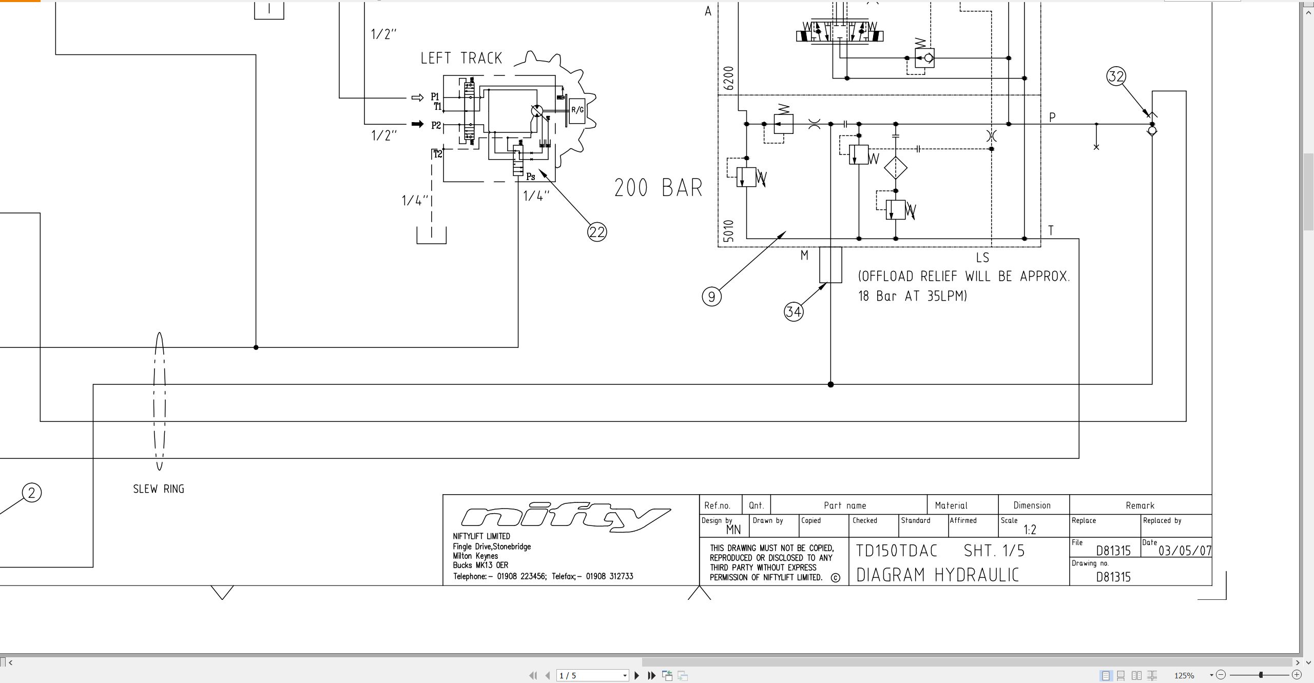
01_TD150T HYDRAULIC DIAGRAM D81315 (issue 003) 39494.pdf (5 Pages)
02_Track Drive matrix D81465 (issue 002) 39494.pdf (1 Pages)
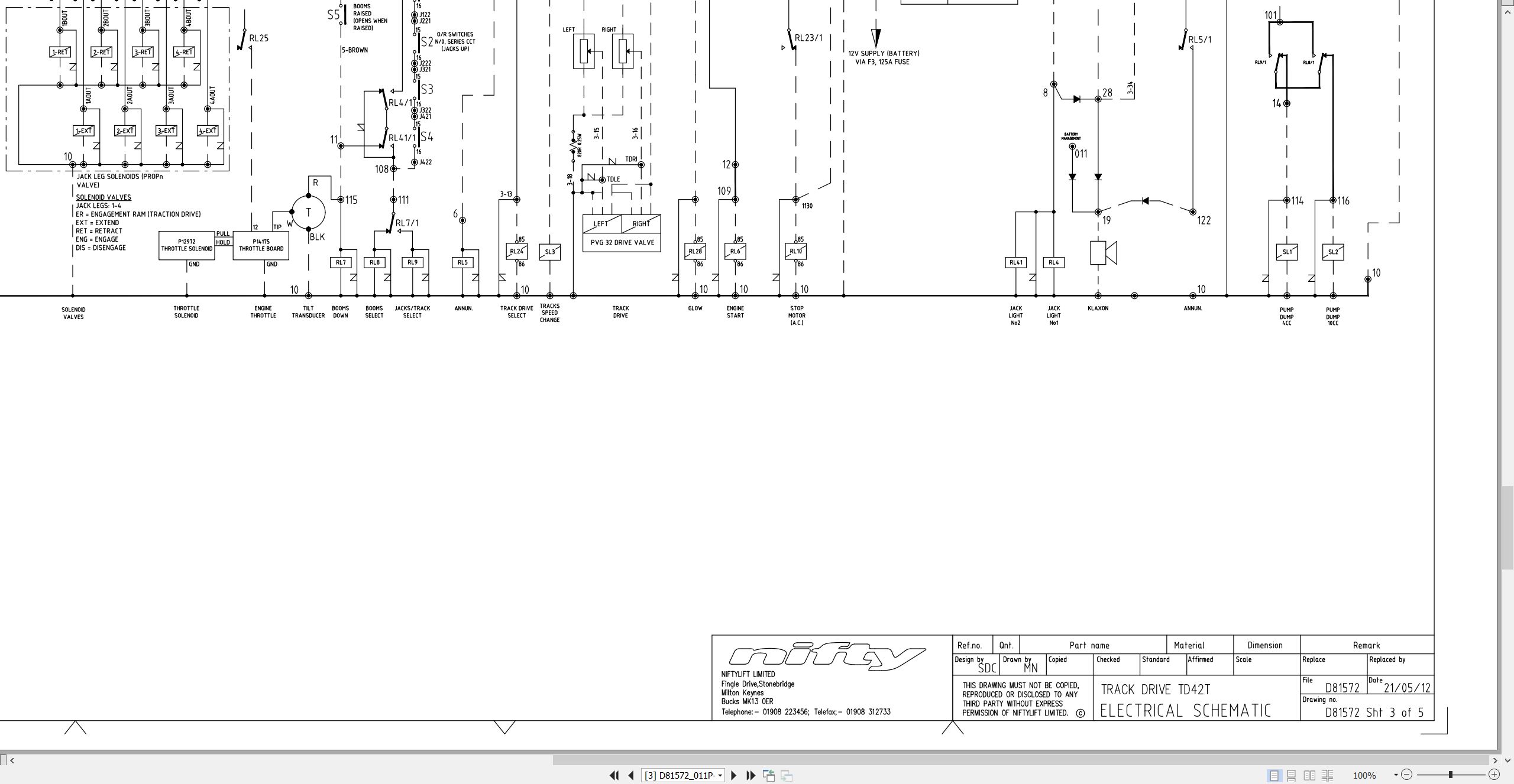
03_CIRCUIT, SCHEMATIC, TD150T USA D81572 (issue 011) 39494.pdf (5 Pages)
04_Kubota D722 Z482 Operators Manual And Wiring Diagram M50291 (issue 002) 39494 1J090-8916-1.pdf (39 Pages)
Contents:
E.pdf
SAFE OPERATION
SERVICING OF THE ENGINE
NAMES OF PARTS
PRE-OPERATION CHECK
BREAK-IN
DAILY CHECK
To prevent trouble from occurring, it is important to know the conditions of the engine well. Che…
OPERATING THE ENGINE
STARTING THE ENGINE(NORMAL)
COLD WEATHER STARTING
STOPPING THE ENGINE
CHECKS DURING OPERATION
REVERSED ENGINE REVOLUTION AND REMEDIES
MAINTENANCE
SERVICE INTERVALS
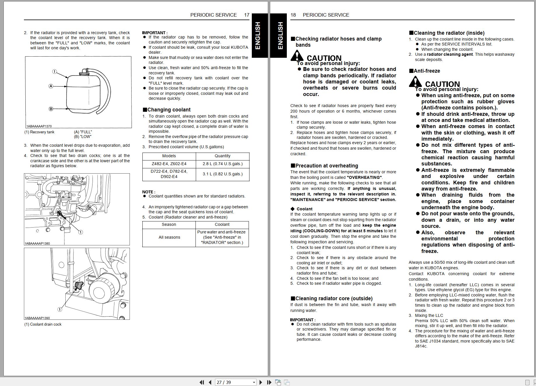
PERIODIC SERVICE
FUEL
ENGINE OIL
RADIATOR
AIR CLEANER
ELECTRIC WIRING
FAN BELT
CARRIAGE AND STORAGE
CARRIAGE
STORAGE
TROUBLESHOOTING
If the engine does not function properly, use the following chart to identify and correct the cause.
SPECIFICATIONS
WIRING DIAGRAMS
05_TD150T TD42T PARTS MANUAL M50322 (issue 003) 39494.pdf (76 Pages)
Contents:
Front Cover
Parts Order Form
Contents
chassis assembly
1.1 Base assembly
1.2 Stabiliser assembly
1.3 Button box assembly
superstructure
2.1 Superstructure assembly
2.2 Diesel engine – Part 1
2.3 Diesel engine – Part 2
2.4 Slew assembly
2.5 Boom rest assembly
2.6 Control valve (4 spool)
2.7 Button box assembly
2.8 Control box assembly
boom assemblies
3.1 Boom 1 assembly
3.2 Telescopic boom assembly
3.3 Lift Cylinder
3.4 Levelling cylinders
3.5 Telescope cylinder
3.6 Levelling valve
cage assembly
4.1 Cage assembly
4.2 Cage weigh assembly
4.3 Control panel assembly
4.4 Control valve (5 spool)
labelling
5.1 Label locations TD150T
Figure 5.1
Labels 1 to 32
Labels 33 to 41
06_TD150T TD42T OPERATING MANUAL UK USA M50334 (issue 003) 39494.pdf (59 Pages)

REALEASE :
REALEASE :

REALEASE :
REALEASE :

REALEASE :
REALEASE :

REALEASE :
REALEASE :

REALEASE :
REALEASE :

REALEASE :
REALEASE :

REALEASE :
REALEASE :

REALEASE :
REALEASE :
 Automotive - Heavy Equipment - Truck & Bus - Forklift - Crane