
1 ITEMVIEW CART

Total: 60.00

Expert Support
Full Speed
100% Working
40 USD
List of Files:
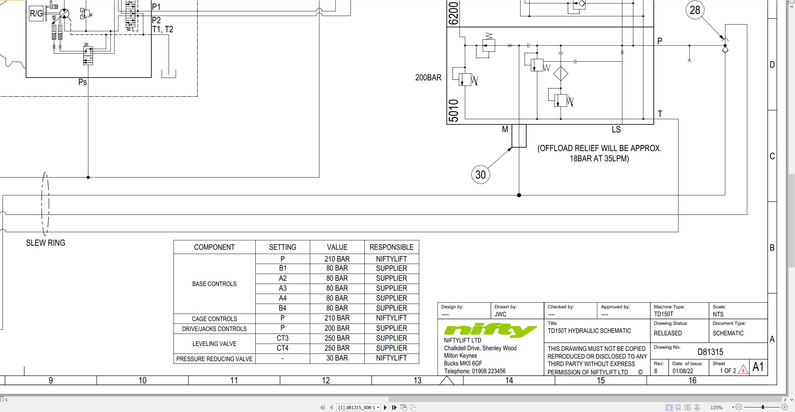
01_TD150T HYDRAULIC DIAGRAM D81315 (issue 008) 55751.pdf (2 Pages)
02_Track Drive matrix D81465 (issue 002) 55751.pdf (1 Pages)
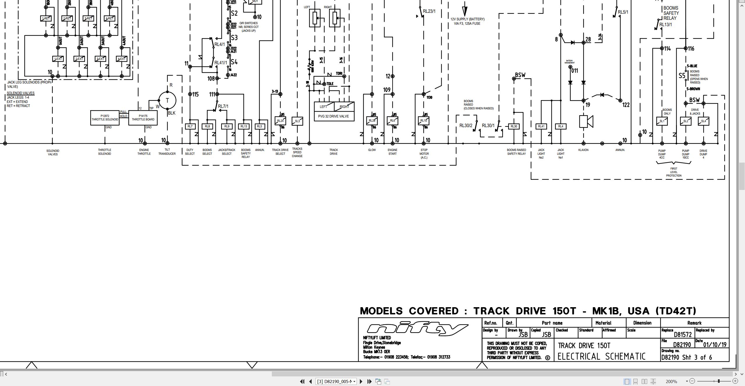
03_ELECTRICAL SCHEMATIC, TD42TDAC D82190 (issue 005) 55751.pdf (6 Pages)
04_Kubota D722 Z482 Operators Manual And Wiring Diagram M50291 (issue 002) 55751 1J090-8916-1.pdf (39 Pages)
Contents:
E.pdf
SAFE OPERATION
SERVICING OF THE ENGINE
NAMES OF PARTS
PRE-OPERATION CHECK
BREAK-IN
DAILY CHECK
To prevent trouble from occurring, it is important to know the conditions of the engine well. Che…
OPERATING THE ENGINE
STARTING THE ENGINE(NORMAL)
COLD WEATHER STARTING
STOPPING THE ENGINE
CHECKS DURING OPERATION
REVERSED ENGINE REVOLUTION AND REMEDIES
MAINTENANCE
SERVICE INTERVALS
PERIODIC SERVICE
FUEL
ENGINE OIL
RADIATOR
AIR CLEANER
ELECTRIC WIRING
FAN BELT
CARRIAGE AND STORAGE
CARRIAGE
STORAGE
TROUBLESHOOTING
If the engine does not function properly, use the following chart to identify and correct the cause.
SPECIFICATIONS
WIRING DIAGRAMS
05_TD150T TD42T PARTS MANUAL M50322 (issue 013) 55751.pdf (82 Pages)
Contents:
Front Cover
Parts Order Form
Contents
chassis assembly
1.1 Base assembly
1.2 Stabiliser assembly
1.3 Button box assembly
superstructure
2.1 Superstructure assembly
2.2 Diesel engine – Part 1
2.3 Diesel engine – Part 2
2.4 Slew assembly
2.5 Boom rest assembly
2.6 Control valve (4 spool)
2.7 Button box assembly
2.8 Control box assembly
2.9 Anderson connector
boom assemblies
3.1 Boom 1 assembly
3.2 Telescopic boom assembly
3.3 Lift Cylinder
3.4 Levelling cylinders
3.5 Telescope cylinder
3.6 Levelling valve
cage assembly
4.1 Cage assembly
4.2 Cage assembly (Fibreglass)
4.3 Cage weigh assembly
4.4 Control panel assembly
4.5 Control valve (5 spool)
labelling
5.1 Label locations
Figure 5.1
Labels 1 to 31
Labels 32 to 47
06_TD 42T SERVICE MANUAL USA M50787 (issue 002) 55751.pdf (59 Pages)
Contents:
1 Introduction and general information
1.1 Foreword
1.1.1 Defined maintenance terms
1.2 Warranty
1.3 Scope
1.4 General maintenance information
1.4.1 Pre-maintenance checks
1.4.2 Maintenance information
1.4.3 Frequent inspection
1.4.4 Annual inspection
1.5 Maintenance safety information
1.5.1 Personal injury prevention
1.5.2 Machine damage prevention
1.5.3 Diesel system safety
1.5.4 Electrical safety
1.5.5 Hydraulic safety
1.5.6 Environmental awareness
2 Specifications
2.1 Engine specifications
2.2 Gearbox specifications
2.3 Fluid properties
2.3.1 Fluid volumes
2.3.2 Engine oil specifications
2.3.3 Engine coolant specifications
2.3.4 Gearbox oil specifications
2.3.5 Hydraulic oil specifications
2.3.6 Hydraulic pressure settings
2.4 Torque settings
2.5 Hydraulic hose and fitting torque specifications
3 Preventative maintenance
3.1 Maintenance schedules
3.1.1 Engine maintenance
3.1.2 Machine maintenance
3.2 Consumables
3.2.1 Data, safety and specification
3.2.2 Access covers and canopies
3.3 Engine maintenance procedures
3.3.1 Engine oil level check
3.3.2 Engine oil replace
3.3.3 Engine oil filter replace
3.3.4 Engine coolant level check (daily)
3.3.5 Engine coolant replace
3.3.6 Coolant hoses and clamp bands check
3.3.7 Antifreeze check
3.3.8 Air filter element maintenance
3.3.9 Fuel filter and water separator clean/replace
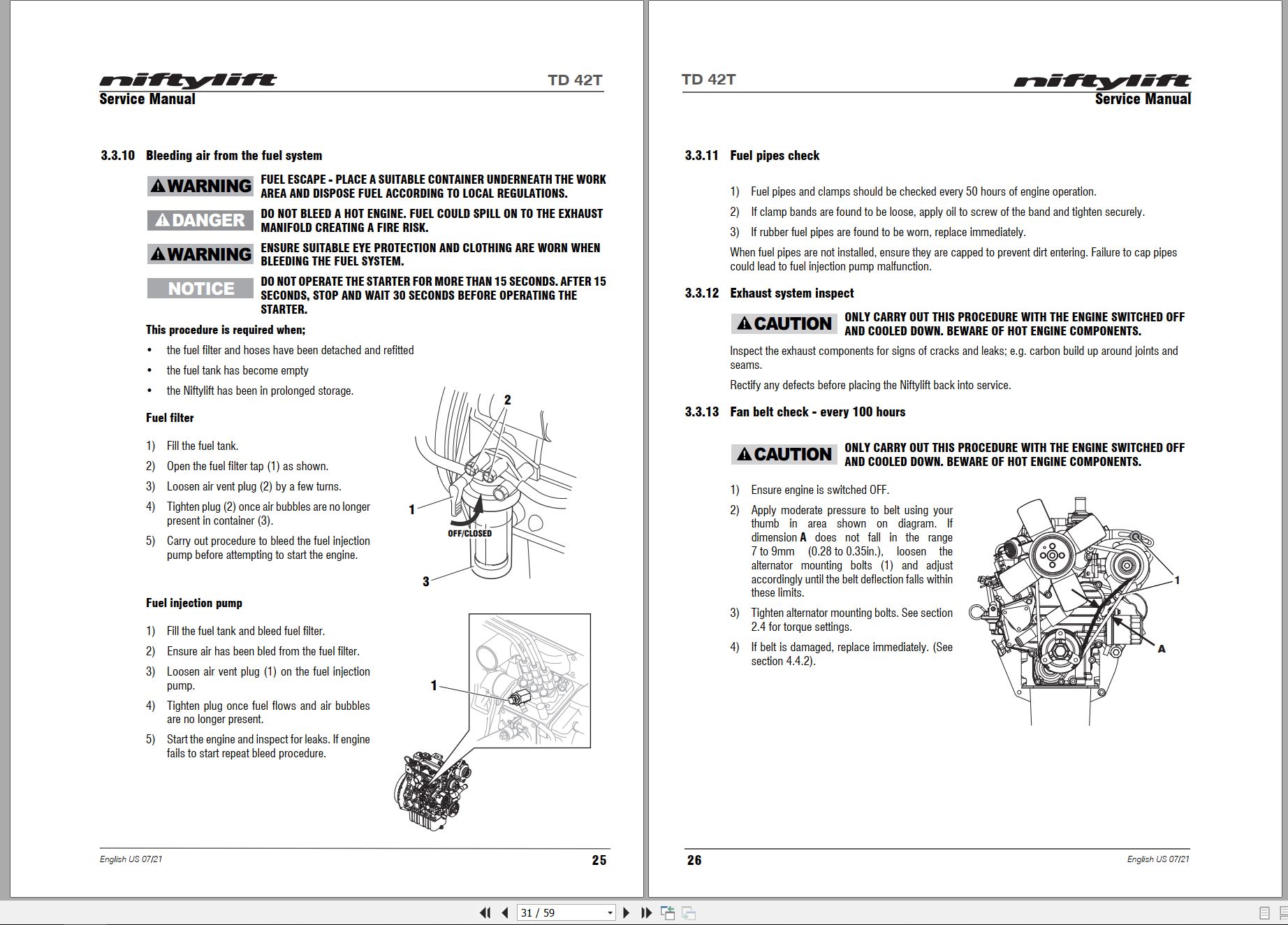
3.3.10 Bleeding air from the fuel system
3.3.11 Fuel pipes check
3.3.12 Exhaust system inspect
3.3.13 Fan belt check – every 100 hours
3.4 Track drive
3.4.1 Track inspection (weekly)
3.4.2 Track tension
3.4.3 Gearbox oil replace
3.5 Stabilizer
3.5.1 Stabilizer foot plate inspection and lubricate (monthly)
3.5.2 Stabilizer pivot pins
3.6 Battery
3.6.1 Condition check (daily/weekly)
3.6.2 Storage
3.7 Hydraulic oil
3.7.1 Level check (weekly)
3.7.2 Pressure filter check (weekly)
3.7.3 Hydraulic oil and filters replace
3.8 Telescopic boom
3.8.1 Wear pad check & lubricate (monthly)
3.8.2 Wear screws check (monthly)
3.8.3 Hose trunking and energy chain check (weekly)
3.8.4 Boom pivot pin check (daily)
3.8.5 Lubricate boom pivot bushes (annually)
3.9 Chassis
3.9.1 Earth strap check (daily)
3.10 Boom rotation gear
3.10.1 Rotation gear engagement check (monthly)
3.10.2 Lubricate Rotation ring (monthly)
3.10.3 Rotation ring bolts check (annually)
4 Repair procedures
4.1 General
4.1.1 Fuses
4.2 Platform/Basket
4.2.1 Footswitch – contact switch replace
4.3 Booms
4.3.1 Energy chain link
4.4 Power tray
4.4.1 Exhaust
4.4.2 Fan belt
4.5 Base assembly
4.5.1 Stabilizer microswitch
5 System overview
5.1 Introduction
5.1.1 Diesel system
5.1.2 AC power system
5.2 Bi-Energy system
5.2.1 Duty selector
5.3 Boom system
5.3.1 Boom switch
5.4 Hydraulic system overview
5.5 Hydraulic pump
5.6 Control logic
6 Troubleshooting guide
6.1 Trouble shooting information
6.2 Platform function fault finding
6.3 Engine fault finding
6.4 Track fault finding
6.5 Gearbox fault finding
07_TD42T OPERATING MANUAL UK USA M50910 (issue 001) 55751.pdf (41 Pages)

REALEASE :
REALEASE :

REALEASE :
REALEASE :

REALEASE :
REALEASE :

REALEASE :
REALEASE :

REALEASE :
REALEASE :

REALEASE :
REALEASE :

REALEASE :
REALEASE :

REALEASE :
REALEASE :
 Automotive - Heavy Equipment - Truck & Bus - Forklift - Crane