
0 ITEMSVIEW CART

✓
Expert Support
✓
Full Speed
✓
100% Working
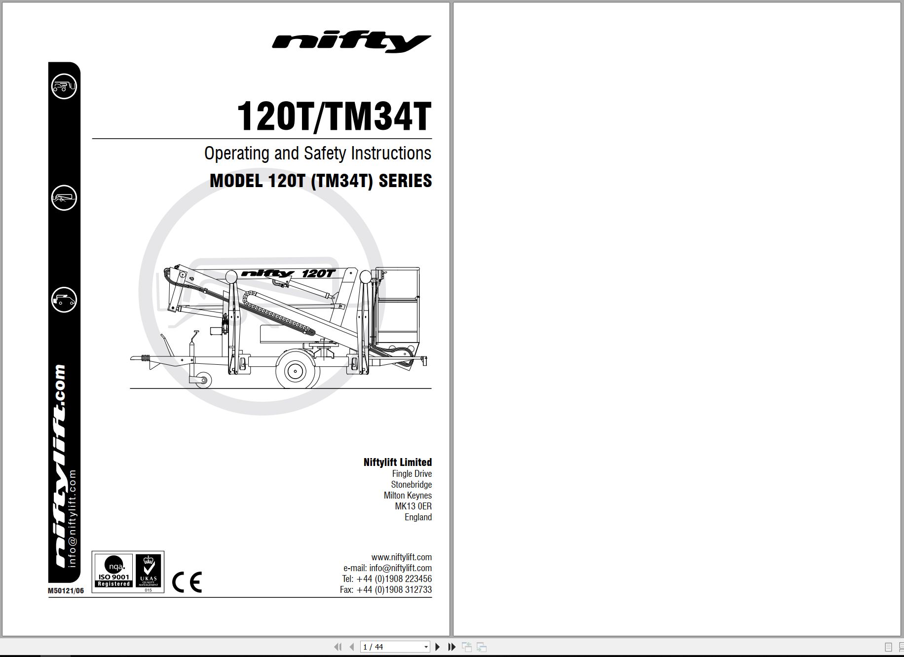
NIFTYLIFT Towable Boom Lifts 120T 26941 Operating Parts Manual And Diagram 2014
Size: 10.21 MB
Format: PDF
Language: English
Brand: NIFTYLIFT
Type of Machine: Towable Boom Lifts
Type of Manual: Operating Manual, Parts Manual, Electrical Schematic, Hydraulic Schematic, Hose Diagram,
Model: NIFTYLIFT 120T Towable Boom Lifts
Serial Number: 26941
Publication Date: 2014
30 USD
- Description
Description
List of Files:
01_HOSE DIAGRAM 120T INSTINCTIVE D80280 (issue 005) 26941.pdf (1 Pages)
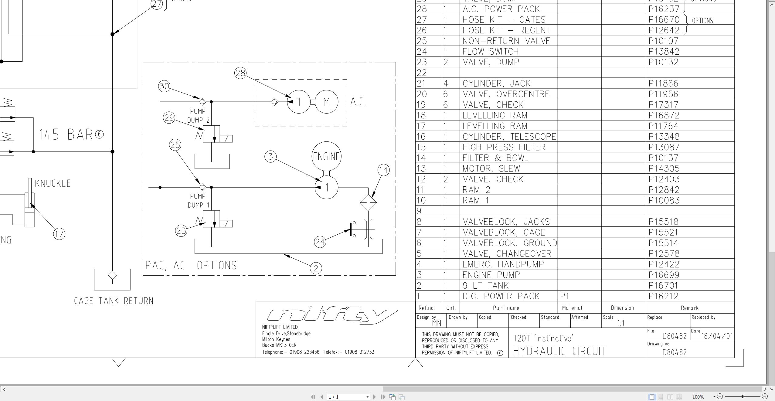
02_HYDRAULIC DIAGRAM 120T INST D80482 (issue 006) 26941.pdf (1 Pages)
03_LIFTING POINTS, 120T D80541 (issue 005) 26941.pdf (2 Pages)
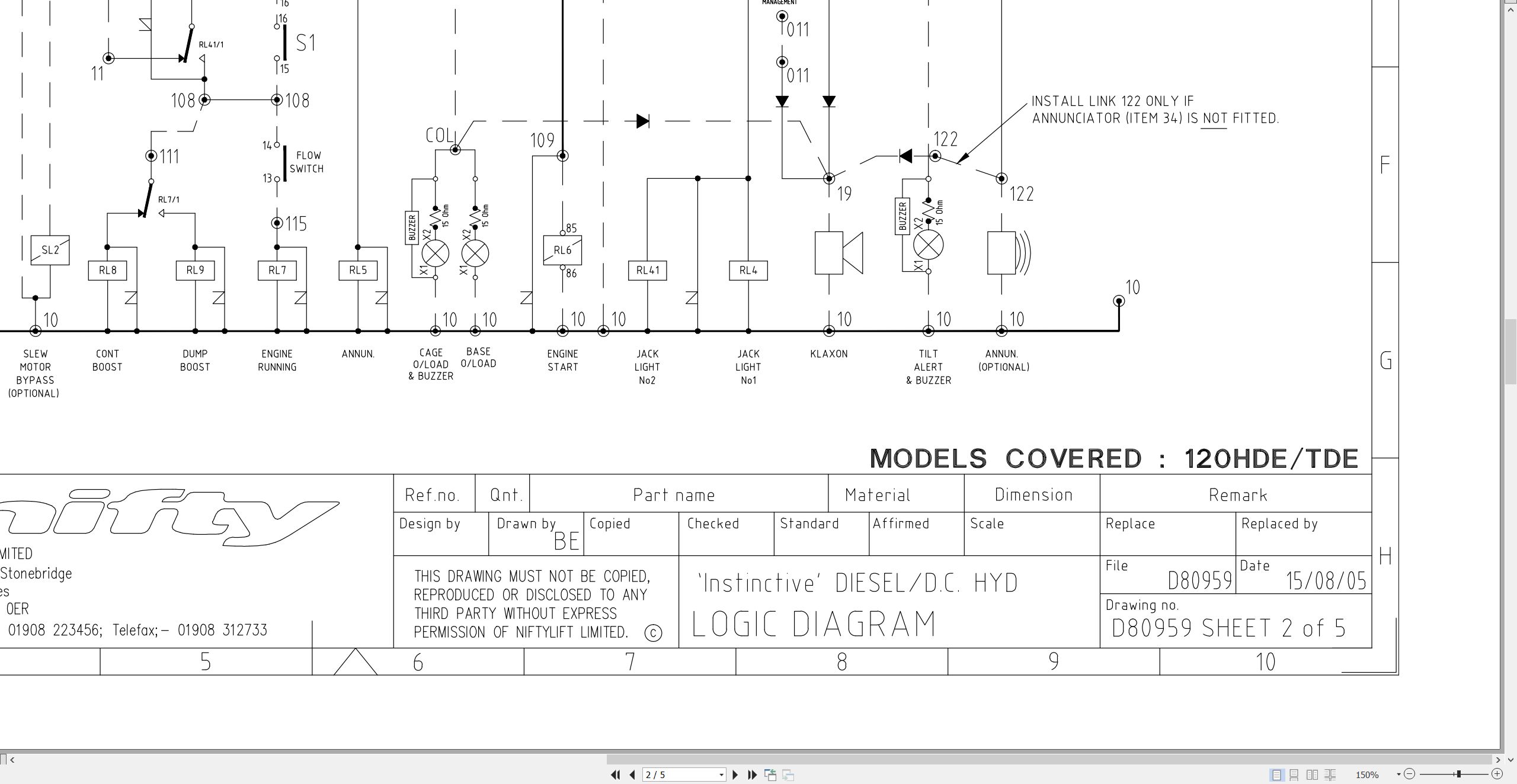
04_WIRING DRG 120H TDE C W D80959 (issue 004) 26941.pdf (5 Pages)
05_120T TM34T PARTS MANUAL M50120 (issue 013) 26941.pdf (128 Pages)
Contents:
chassis assembly
1.1 Base assembly – Sliding axle
1.2 Base assembly – Fixed axle
1.3 Traction drive assembly
1.4 Stabiliser assembly
1.5 Tow coupling assembly
1.6 Jockey wheel assembly
1.7 Heavy duty jockey wheel
1.8 Lighting assemblies
1.9 Wheel hub assembly
1.10 Valve block (Traction drive)
superstructure
2.1 Power tray (P/D/E/PE)
2.2 Power tray (AC/DC)
2.3 Power tray (AC)
2.4 Slew assembly
2.5 Control valve assembly (3 spool)
2.6 Control valve assembly (4 spool)
2.7 Button box assemblies (Base)
2.8 PCB Control box
2.9 AC transformer box
2.10 AC/DC transformer box
2.11 DC Power pack
2.12 AC Power pack
2.13 DC Power pack (AC/DC machine)
2.14 Battery charger (UK)
2.15 Battery charger (Euro/Australia & USA)
boom assemblies
3.1 Booms assembly
3.2 Lift cylinder
3.3 Levelling cylinder
3.4 Telescope cylinder
3.5 Energy chain
cage assembly
4.1 Cage assembly
4.2 Cage assembly (Fibreglass)
4.3 Cage weigh assembly (Spring)
4.4 Cage weigh assembly (Load Cell)
4.5 Control valve assembly (Cage)
4.6 Button box assemblies (Cage)
labelling
5.1 Label locations 120T
5.2 Label locations TM34T
Labels 1-32
Labels 33-50
hydraulic hoses
6.1 Hose kit 120T (TM34T)
6.2 Traction Drive Kit (P14205)
06_120T TM34T OPERATING MANUAL UK USA M50121 (issue 006) 26941.pdf (44 Pages)
Related Products
-
NIFTYLIFT Towable Boom Lifts TM64 55045 Operators Service Manual Diagram 2023
40 USDSize: 28.66 MBFormat: PDFLanguage: EnglishBrand: NIFTYLIFTType of Machine: Towable Boom LiftsType of Manual: Service Manual, Operating Manual, Parts Manual, Electrical SchematicModel: NIFTYLIFT TM64 Towable Boom LiftsSerial Number: 55045Publication Date: 2023
REALEASE :
REALEASE :
-
NIFTYLIFT Towable Boom Lifts TM64 52414 Operating Service Parts Manual And Diagram 2022
40 USDSize: 29.17 MBFormat: PDFLanguage: EnglishBrand: NIFTYLIFTType of Machine: Towable Boom LiftsType of Manual: Service Manual, Operating Manual, Parts Manual, Electrical Schematic, Hydraulic Schematic,Model: NIFTYLIFT TM64 Towable Boom LiftsSerial Number: 52414Publication Date: 2022
REALEASE :
REALEASE :
-
NIFTYLIFT Towable Boom Lifts TM64 56064 Operating Service Parts Manual And Diagram 2023
40 USDSize: 28.80 MBFormat: PDFLanguage: EnglishBrand: NIFTYLIFTType of Machine: Towable Boom LiftsType of Manual: Service Manual, Operating Manual, Inspection Manual, Parts Manual, Electrical Schematic, Hydraulic Schematic,Model: NIFTYLIFT TM64 Towable Boom LiftsSerial Number: 56064Publication Date: 2023
REALEASE :
REALEASE :
-
NIFTYLIFT Towable Boom Lifts TM50 58728 Operating Service Parts Manual And Diagram 2025
50 USDSize: 20.05 MBFormat: PDFLanguage: EnglishBrand: NIFTYLIFTType of Machine: Towable Boom LiftsType of Manual: Service Manual, Operating Manual, Parts Manual, Electrical Schematic, Hydraulic Schematic,Model: NIFTYLIFT TM50 Towable Boom LiftsSerial Number: 58728Publication Date: 2025
REALEASE :
REALEASE :
-
NIFTYLIFT Towable Boom Lifts TM50 56720 Operating Service Parts Manual And Diagram 2025
50 USDSize: 27.98 MBFormat: PDFLanguage: EnglishBrand: NIFTYLIFTType of Machine: Towable Boom LiftsType of Manual: Service Manual, Operating Manual, Parts Manual, Electrical Schematic, Hydraulic Schematic,Model: NIFTYLIFT TM50 Towable Boom LiftsSerial Number: 56720Publication Date: 2025
REALEASE :
REALEASE :
-
NIFTYLIFT Towable Boom Lifts TM50 57219 Operating Service Parts Manual And Diagram 2025
50 USDSize: 27.83 MBFormat: PDFLanguage: EnglishBrand: NIFTYLIFTType of Machine: Towable Boom LiftsType of Manual: Service Manual, Operating Manual, Parts Manual, Electrical Schematic, Hydraulic Schematic,Model: NIFTYLIFT TM50 Towable Boom LiftsSerial Number: 57219Publication Date: 2025
REALEASE :
REALEASE :
-
NIFTYLIFT Towable Boom Lifts TM50 56687 Operating Service Parts Manual And Diagram 2025
50 USDSize: 20.05 MBFormat: PDFLanguage: EnglishBrand: NIFTYLIFTType of Machine: Towable Boom LiftsType of Manual: Service Manual, Operating Manual, Parts Manual, Electrical Schematic, Hydraulic Schematic,Model: NIFTYLIFT TM50 Towable Boom LiftsSerial Number: 56687Publication Date: 2025
REALEASE :
REALEASE :
-
NIFTYLIFT Towable Boom Lifts TM64 55060 Operating Service Parts Manual And Diagram 2023
40 USDSize: 28.83 MBFormat: PDFLanguage: EnglishBrand: NIFTYLIFTType of Machine: Towable Boom LiftsType of Manual: Service Manual, Operating Manual, Parts Manual, Electrical Schematic, Hydraulic Schematic,Model: NIFTYLIFT TM64 Towable Boom LiftsSerial Number: 55060Publication Date: 2023
REALEASE :
REALEASE :