
3 ITEMSVIEW CART


Total: 370.00
Expert Support
Full Speed
100% Working
40 USD
List of Files:
01_HOSE DIAGRAM 120T INSTINCTIVE D80280 (issue 005) 43631.pdf (1 Pages)
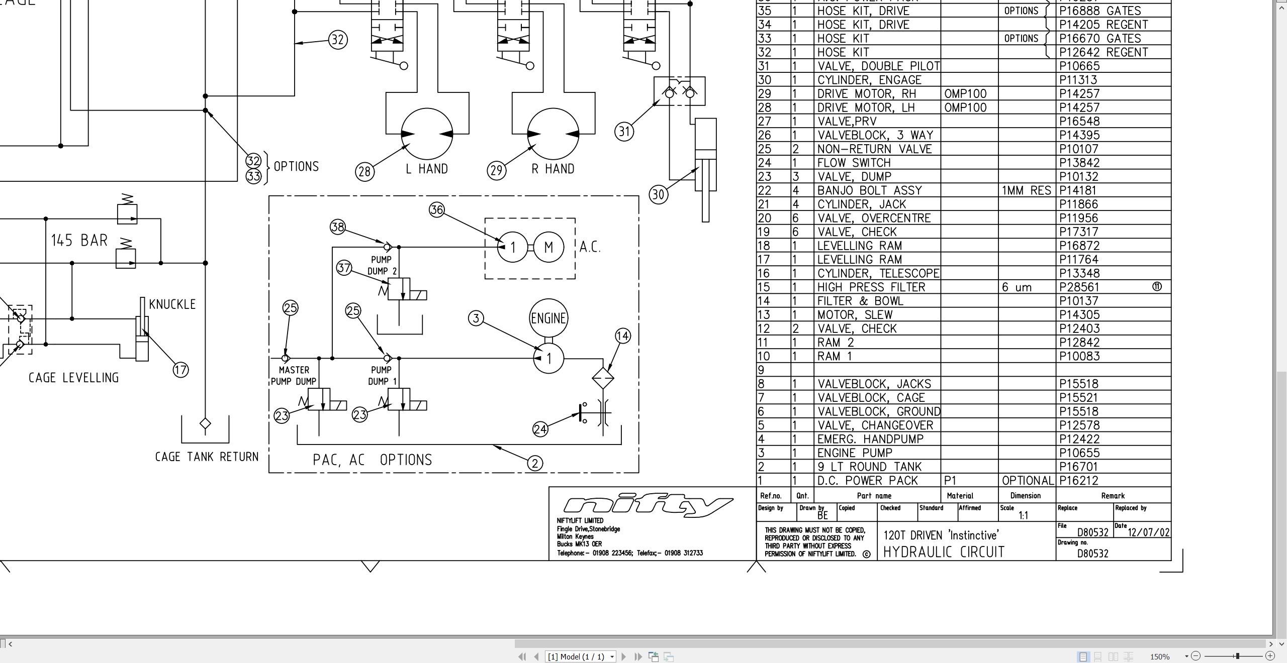
02_HYD CIRCUIT 120T DRIVEN INSTINCTIVE D80532 (issue 011) 43631.pdf (1 Pages)
03_LIFTING POINTS, 120T D80541 (issue 005) 43631.pdf (2 Pages)
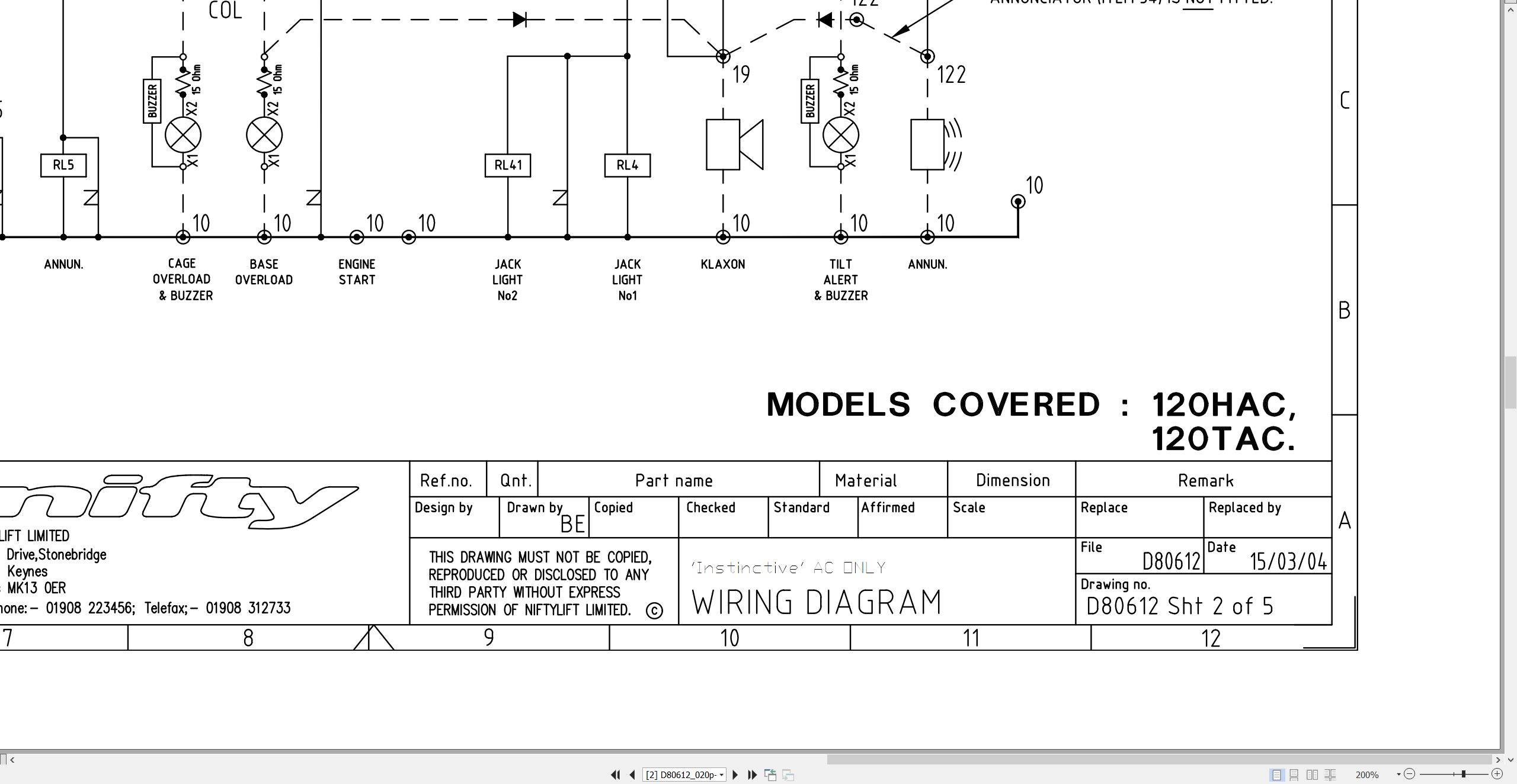
04_WIRING DIAGRAM 120TAC- UK EN280 C. WEIGH D80612 (issue 020) 43631.pdf (5 Pages)
05_120T TM34T PARTS MANUAL M50120 (issue 018) 43631.pdf (128 Pages)
Contents:
chassis assembly
1.1 Base assembly – Sliding axle
1.2 Base assembly – Fixed axle
1.3 Traction drive assembly
1.4 Stabiliser assembly
1.5 Tow coupling assembly
1.6 Jockey wheel assembly
1.7 Heavy duty jockey wheel
1.8 Lighting assemblies
1.9 Wheel hub assembly
1.10 Valve block (Traction drive)
superstructure
2.1 Power tray (P/D/E/PE)
2.2 Power tray (AC/DC)
2.3 Power tray (AC)
2.4 Power tray (DC – Lithium)
2.5 Slew assembly
2.6 Control valve assembly (3 spool)
2.7 Control valve assembly (4 spool)
2.8 Button box assemblies
2.9 PCB Control box
2.10 AC transformer box
2.11 AC/DC transformer box
2.12 DC Power pack
2.13 AC Power pack
2.14 DC Power pack (AC/DC machine)
2.15 Battery charger (UK)
2.16 Battery charger (Euro/Australia & USA)
boom assemblies
3.1 Booms assembly
3.2 Lift cylinder
3.3 Levelling cylinder
3.4 Telescope cylinder
3.5 Energy chain
cage assembly
4.1 Cage assembly
4.2 Cage assembly (Fibreglass)
4.3 Cage weigh assembly
4.4 Control valve assembly (Cage)
4.5 Button box assemblies
labelling
5.1 Label locations 120T
5.2 Label locations TM34T
Labels 1-31
Labels 32-52
hydraulic hoses
6.1 Hose kit 120T (TM34T)
6.2 Traction Drive Kit (P14205)
06_120T TM34T OPERATING MANUAL UK USA M50121 (issue 009) 43631.pdf (55 Pages)
07_120T SERVICE MANUAL M50570 (issue 001) 43631.pdf (65 Pages)
Contents:
1 Introduction and general information
1.1 Foreword
1.1.1 Defined maintenance terms
1.2 Warranty
1.3 Scope
1.4 General maintenance information
1.4.1 Pre-maintenance checks
1.4.2 Maintenance information
1.4.3 Frequent inspection
1.4.4 Annual inspection
1.5 Maintenance safety information
1.5.1 Personal injury prevention
1.5.2 Machine damage prevention
1.5.3 Diesel system safety
1.5.4 Electrical safety
1.5.5 Hydraulic safety
1.5.6 Environmental awareness
2 Specifications
2.1 Engine specifications
2.2 Fluid properties
2.2.1 Fluid volumes
2.2.2 Engine oil specifications
2.2.3 Hydraulic oil specifications
2.2.4 Hydraulic pressure settings
2.3 Tyre specifications
2.4 Torque settings
2.5 Hydraulic hose and fitting torque specifications
3 Preventative maintenance
3.1 Maintenance schedules
3.1.1 Engine maintenance
3.1.2 Machine maintenance
3.2 Consumables
3.2.1 Data, safety and specification
3.3 Engine maintenance procedures
3.3.1 Engine oil level check
3.3.2 Engine oil replace
3.3.3 Engine oil filter replace
3.3.4 Air filter element maintenance
3.3.5 Fuel filter and fuel tank maintenance
3.3.6 Fuel injector nozzle
3.3.7 Sediment cup
3.3.8 Cylinder compression
3.3.9 Fuel hoses
3.3.10 Exhaust system inspect
3.3.11 Valve clearance
3.3.12 Combustion chamber
3.3.13 Spark plug
3.3.14 Spark arrester
3.4 Wheels and tyres
3.4.1 Tyre condition check
3.4.2 Tyre pressure check
3.4.3 Wheel nut / bolt torque
3.5 Axle suspension
3.5.1 Axle inspection
3.6 Traction drive
3.7 Tow hitch
3.8 Braking system
3.8.1 Brake adjustment
3.9 Mudguards
3.10 Stabilisers
3.10.1 Stabiliser foot plate inspection and lubricate (monthly)
3.10.2 Stabiliser pivot pins
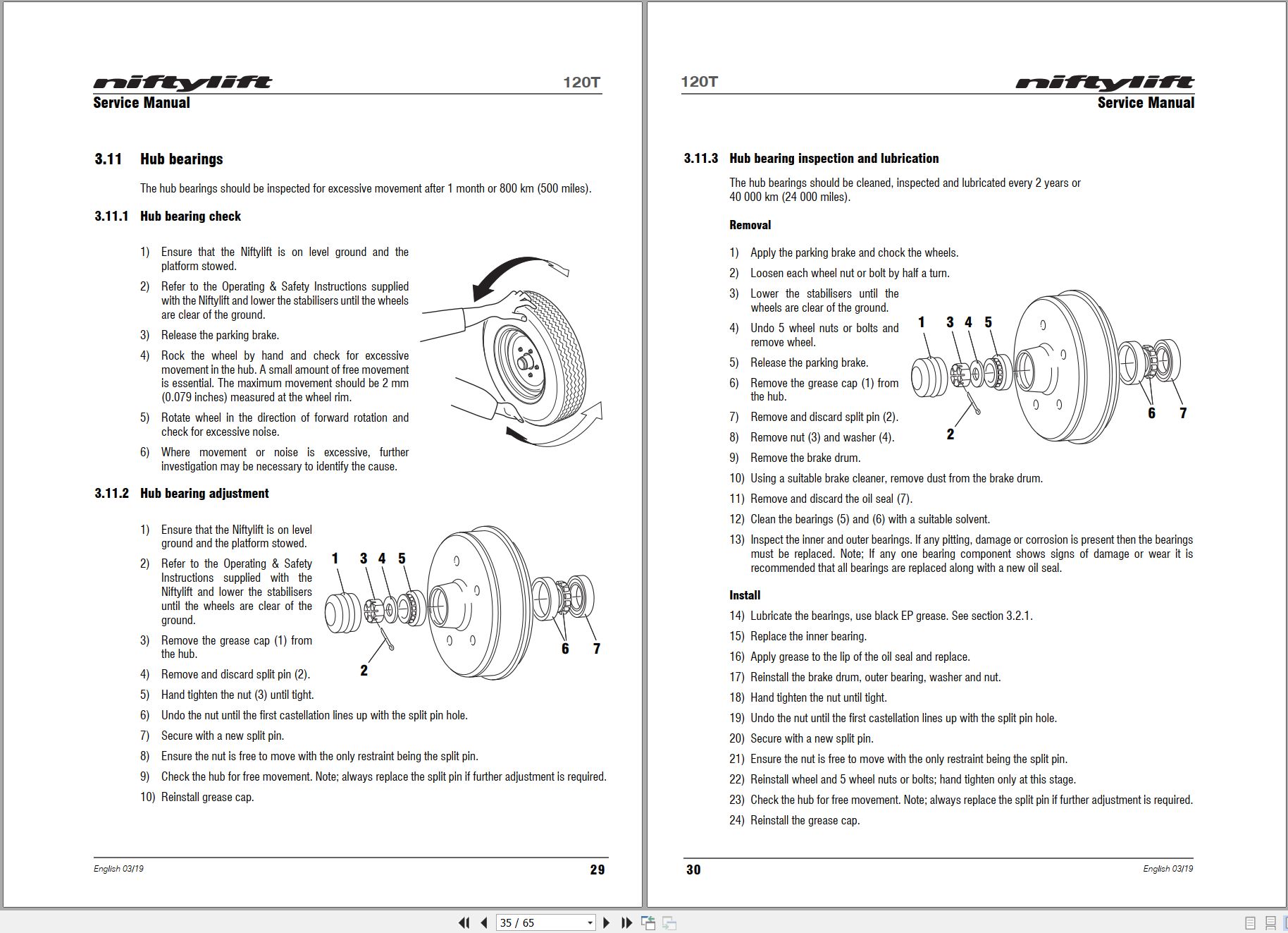
3.11 Hub bearings
3.11.1 Hub bearing check
3.11.2 Hub bearing adjustment
3.11.3 Hub bearing inspection and lubrication
3.12 Lighting
3.12.1 Bulb replacement
3.13 Batteries
3.13.1 Condition check (daily)
3.13.2 Condition check (weekly) – excludes AGM & Li-ion batteries
3.13.3 Storage
3.14 Hydraulic oil
3.14.1 Level check (weekly)
3.14.2 Pressure filter check (weekly)
3.14.3 Hydraulic oil and filters replace
3.15 Telescopic boom
3.15.1 Wear pad check & lubricate (monthly)
3.15.2 Hose trunking and energy chain check (weekly)
3.15.3 Boom pivot pin check (daily)
3.15.4 Lubricate boom pivot bushes (annually)
3.16 Boom rotation gear
3.16.1 Slew gear engagement check (monthly)
3.16.2 Lubricate slew ring (monthly)
3.16.3 Slew ring bolts check (annually)
4 Repair procedures
4.1 General
4.1.1 Fuses
4.2 Platform/Cage
4.2.1 Footswitch – contact switch replace
4.3 Booms
4.3.1 Energy chain link
4.4 Base assembly
4.4.1 Stabiliser microswitch
4.5 Axle
4.5.1 Brake shoe replacement
5 System overview
5.1 Introduction
5.1.1 Diesel / petrol system
5.1.2 DC electric system
5.1.3 AC power system
5.1.4 AC/DC power system
5.2 Charging and batteries
5.2.1 Battery charging – extension leads
5.3 Bi-Energy system
5.3.1 Duty selector
5.4 Boom system
5.4.1 Boom switch
5.5 Hydraulic system overview
5.6 Hydraulic pump
5.7 Control logic
6 Troubleshooting guide
6.1 Trouble shooting information
6.2 Platform function fault finding
6.3 Engine fault finding
6.3.1 Diesel engine
6.3.2 Petrol engine
6.4 Li-ion battery system
6.5 Braking system

REALEASE :
REALEASE :

REALEASE :
REALEASE :

REALEASE :
REALEASE :

REALEASE :
REALEASE :

REALEASE :
REALEASE :

REALEASE :
REALEASE :

REALEASE :
REALEASE :

REALEASE :
REALEASE :
 Automotive - Heavy Equipment - Truck & Bus - Forklift - Crane