")
Expert Support
Full Speed
100% Working
NIFTYLIFT Towable Boom Lifts 170 23545 Operating Parts Manual And Diagram 2012 EN NL
30 USD
- Description
Description
List of Files:
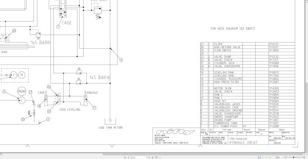
01_HYDRAULIC DIAGRAM 170H INST D80483 (issue 007) 23545.pdf (1 Pages)
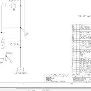
02_HOSE DIAGRAM 170H INSTINCTIVE D80571 (issue 004) 23545.pdf (1 Pages)
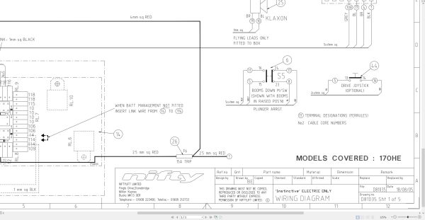
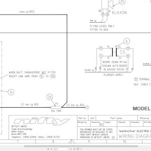
03_ELECTRICAL SCHEMATIC 170HE MECH CW D81035 (issue 003) 23545.pdf (1 Pages)
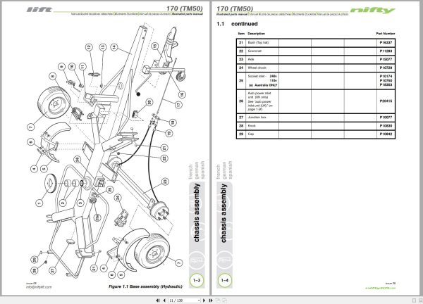
04_170 TM50 PARTS MANUAL M50150 (issue 009) 23545.pdf (138 Pages)
Contents:
Introduction
Parts Order Form
Contents
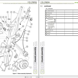
chassis assembly
1.1 Base assembly (Hydraulic)
1.2 Base assembly (Manual)
1.3 Traction drive assembly
1.4 Stabiliser assembly
1.5 Manual jack assembly
1.6 Tow coupling assembly
1.7 Heavy duty jockey wheel
1.8 Lighting assemblies
1.9 Wheel hub assembly
1.10 Wheel hub assembly (Traction drive)
1.11 Valve block (Traction drive)
1.12 auto power inlet unit (UK)
superstructure
2.1 Power tray (Petrol/Diesel/Bi-energy)
2.2 Power tray (AC/Mains)
2.3 Slew assembly
2.4 Control valve assembly (3 spool)
2.5 Control valve assembly (4 spool)
2.6 Button box assemblies (Base)
2.7 Control box
2.8 Diesel box
2.9 AC transformer box
2.10 DC Power pack
2.11 DC Power pack (Traction Drive)
2.12 AC Power pack
2.13 Diesel engine (Kubota OC60)
2.14 Anderson connector
boom assemblies
3.1 Upper boom assembly
3.2 Lower boom assembly
3.3 Lift cylinder
3.4 Levelling cylinder
3.5 Telescope cylinder
3.6 Levelling valve
cage assembly
4.1 Swivel cage assembly
4.2 Non-swivel cage assembly
4.3 Cage assembly (Fibreglass)
4.4 Swivel cage weigh assembly (Spring)
4.5 Swivel cage weigh assembly (Load Cell)
4.6 Non-swivel cage weigh assembly – (Spring)
4.7 Non- swivel cage weigh assembly (Load Cell)
4.8 Control valve assembly
4.9 Button box assemblies (Cage)
labelling
5.1 Label locations 170
5.2 Label locations TM50 (USA)
Labels (1 to 28)
Labels (29 to 45)
hydraulic hoses
6.1 Hose kit 170H (TM50)
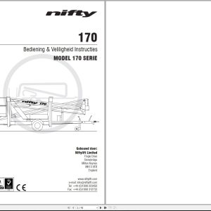
05_170 OPERATING MANUAL DUTCH M50153 (issue 008) 23545.pdf (43 Pages)
Related Products
-
NIFTYLIFT Towable Boom Lifts TM64 56064 Operating Service Parts Manual And Diagram 2023
40 USD -
NIFTYLIFT Towable Boom Lifts TM64 55060 Operating Service Parts Manual And Diagram 2023
40 USD -
NIFTYLIFT Towable Boom Lifts TM64 52414 Operating Service Parts Manual And Diagram 2022
40 USD -
NIFTYLIFT Towable Boom Lifts TM50 56720 Operating Service Parts Manual And Diagram 2025
50 USD -
NIFTYLIFT Towable Boom Lifts TM64 55045 Operators Service Manual Diagram 2023
40 USD -
NIFTYLIFT Towable Boom Lifts TM50 56687 Operating Service Parts Manual And Diagram 2025
50 USD -
NIFTYLIFT Towable Boom Lifts TM50 57219 Operating Service Parts Manual And Diagram 2025
50 USD -
NIFTYLIFT Towable Boom Lifts TM50 58728 Operating Service Parts Manual And Diagram 2025
50 USD