
0 ITEMSVIEW CART

✓
Expert Support
✓
Full Speed
✓
100% Working
NIFTYLIFT Towable Boom Lifts 170 45554 Operating Service Parts Manual And Diagram 2020
Size: 19.51 MB
Format: PDF
Language: English
Brand: NIFTYLIFT
Type of Machine: Towable Boom Lifts
Type of Manual: Service Manual, Operating Manual, Parts Manual, Electrical Schematic, Hydraulic Schematic, Hose Diagram
Model: NIFTYLIFT 170 Towable Boom Lifts
Serial Number: 45554
Publication Date: 2020
40 USD
- Description
Description
List of Files:
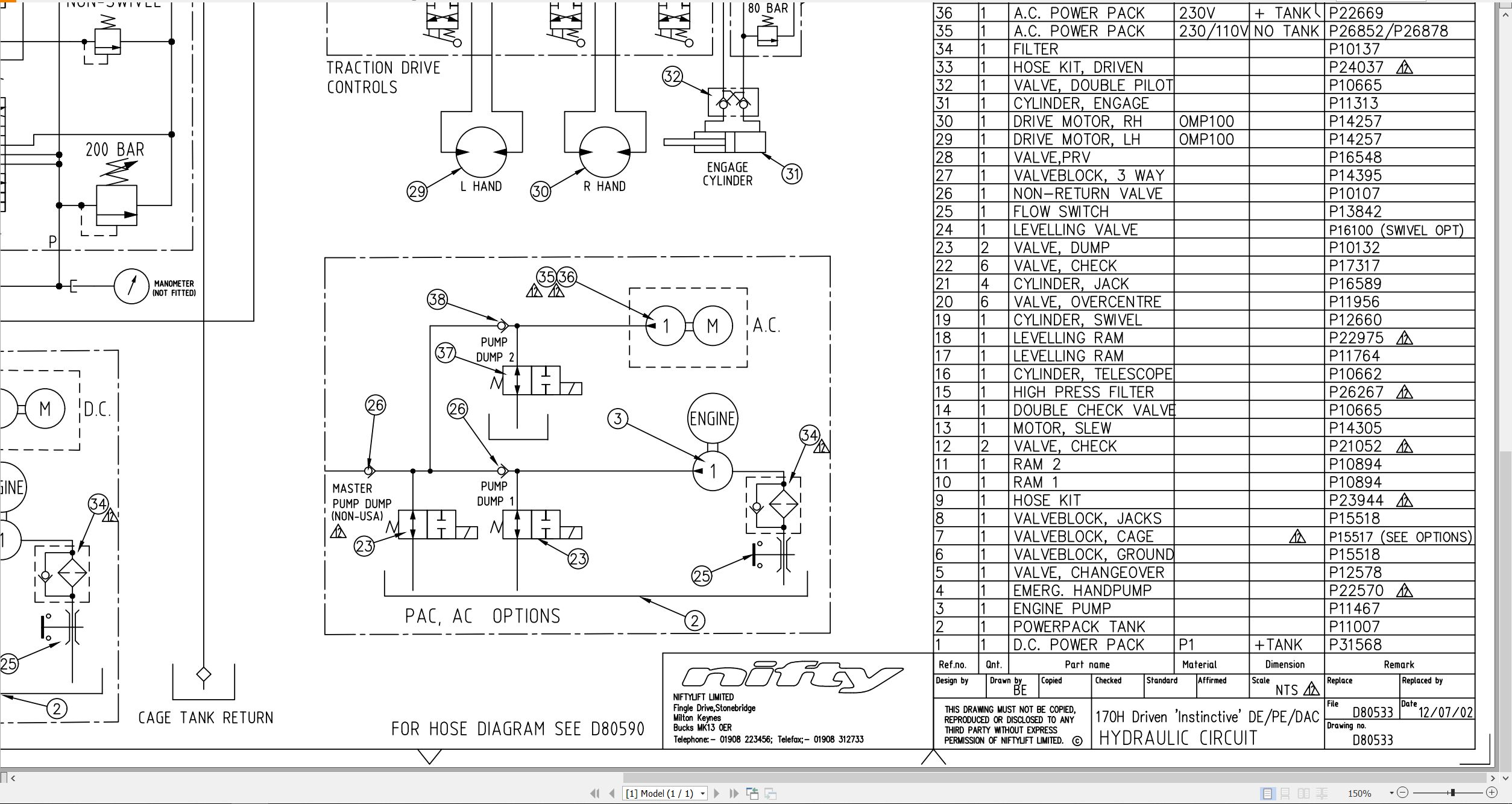
01_HYD CIRCUIT 170H DRIVEN INSTINCT D80533 (issue 012) 45554.pdf (1 Pages)
02_HOSE DIAGRAM 170H DRIVEN D80590 (issue 004) 45554.pdf (1 Pages)
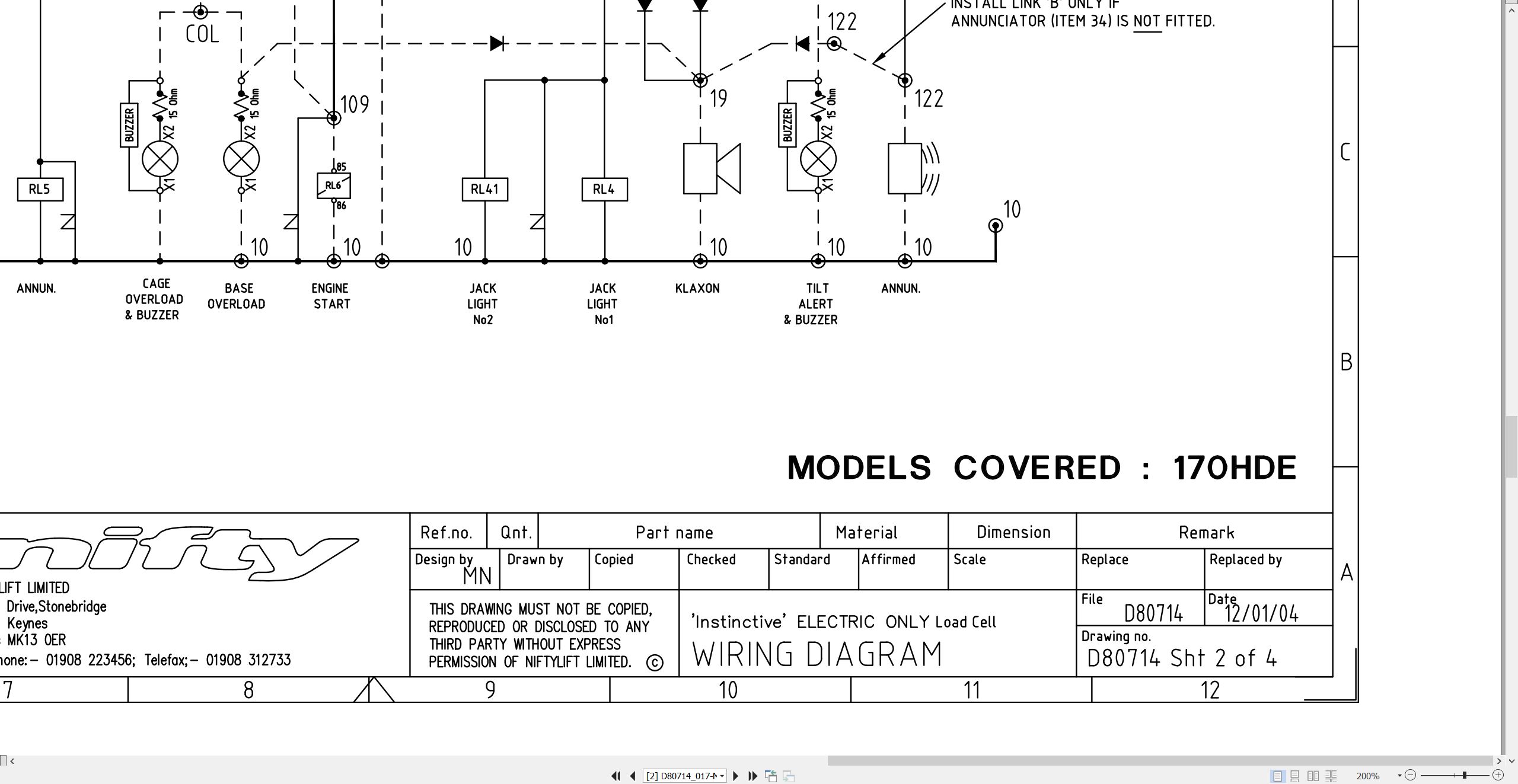
03_ELEC SCHEMATIC 170HDE UK EN280 C W D80714 (issue 017) 45554.pdf (4 Pages)
Contents:
Sheets and Views
04_LIFTING POINTS, 170H D80906 (issue 004) 45554.pdf (2 Pages)
Contents:
Sheets and Views
05_170 TM50 PARTS MANUAL M50150 (issue 016) 45554.pdf (132 Pages)
Contents:
Front cover
Parts Order Form
chassis assembly
1.1 Base assembly
1.2 Traction drive assembly
1.3 Bike bar assemblies
1.4 Stabiliser assembly
1.5 Tow coupling assembly
1.6 Heavy duty jockey wheel
1.7 Lighting assemblies
1.8 Wheel hub assembly
1.9 Wheel hub assembly (Axle P15305)
1.10 Valve block (Traction drive)
1.11 auto power inlet unit (UK)
superstructure
2.1 Power tray (Petrol/Diesel/Bi-energy)
2.2 Power tray (AC/Mains)
2.3 Power tray (DC – Lithium)
2.4 Slew assembly
2.5 Control valve assembly (3 spool)
2.6 Control valve assembly (4 spool)
2.7 Button box assemblies
2.8 Control box
2.9 Diesel box
2.10 AC transformer box
2.11 DC Power pack
2.12 DC Power pack (Traction Drive)
2.13 AC Power pack
2.14 Diesel engine (Kubota OC60)
2.15 Anderson connector
boom assemblies
3.1 Upper boom assembly
3.2 Lower boom assembly
3.3 Lift cylinder
3.4 Levelling cylinder
3.5 Telescope cylinder
3.6 Levelling valve
cage assembly
4.1 Non-swivel cage assembly
4.2 Swivel cage assembly (Option)
4.3 Cage assembly (Fibreglass)
4.4 Non- swivel cage weigh assembly
4.5 Swivel cage weigh assembly
4.6 Control valve assembly
4.7 Button box assembly
labelling
5.1 Label locations 170
5.2 Label locations TM50 (USA)
Labels 1 to 31
Labels 30 to 52
hydraulic hoses
6.1 Hose kit 170H (TM50)
06_170 TM50 OPERATING MANUAL UK USA M50151 (issue 012) 45554.pdf (57 Pages)
07_Kubota OC60 95 Operators Manual And Wiring Diagram M50290 (issue 002) 45554 11551-8915-6.pdf (2 Pages)
Contents:
OPS BROCHURE – KUBOTA DIESEL AC60 OC60 / 80 / 95 (11551-8915-6)
FOREWORD
SAFETY FIRST
SAFE OPERATION
REQUESTING SERVICING
SPECIFICATIONS
PERIODIC SERVICE
BATTERY
PULLEY
WIRING DIAGRAM
GENUINE REGULATOR INSTALLATION EXAMPLE
HOW TO HOIST UP THE ENGINE
PRE-START CHECKS
CAPACITY
FUEL
CRANKCASE OIL
STARTING AND OPERATION
STARTING – ELECTRIC STARTING MODEL
STARTING – RECOIL STARTING MODEL
STARTING LOW TEMPERATURES – RECOIL STARTING MODEL
OPERATION
MAINTENANCE – REFER TO PERIODIC SERVICE
THE FUEL FILTER
THE CRANKCASE OIL
THE AIR CLEANER
THE OIL COOLER
THE RUBBER HOSE
PRECAUTIONS AT RECOIL STARTING
STOPPING
STORAGE
KUBOTA CONTACT DETAILS
08_170 SERVICE MANUAL M50592 (issue 001) 45554.pdf (69 Pages)
Contents:
1 Introduction and general information
1.1 Foreword
1.1.1 Defined maintenance terms
1.2 Warranty
1.3 Scope
1.4 General maintenance information
1.4.1 Pre-maintenance checks
1.4.2 Maintenance information
1.4.3 Frequent inspection
1.4.4 Annual inspection
1.5 Maintenance safety information
1.5.1 Personal injury prevention
1.5.2 Machine damage prevention
1.5.3 Diesel system safety
1.5.4 Electrical safety
1.5.5 Hydraulic safety
1.5.6 Environmental awareness
2 Specifications
2.1 Engine specifications
2.2 Fluid properties
2.2.1 Fluid volumes
2.2.2 Engine oil specifications
2.2.3 Hydraulic oil specifications
2.3 Hydraulic pressure settings
2.4 Tyre specifications
2.5 Torque settings
2.5.1 Torque Settings – Kubota OC60 engine
2.6 Hydraulic hose and fitting torque specifications
3 Preventative maintenance
3.1 Maintenance schedules
3.1.1 Engine maintenance
3.1.2 Machine maintenance
3.2 Consumables
3.2.1 Data, safety and specification
3.2.2 Engine oil level check
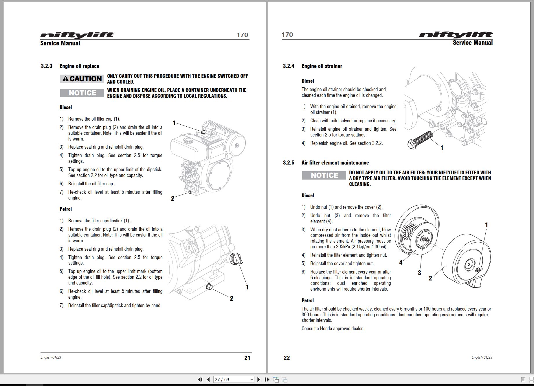
3.2.3 Engine oil replace
3.2.4 Engine oil strainer
3.2.5 Air filter element maintenance
3.2.6 Fuel filter clean / replace
3.2.7 Fuel pipe check
3.2.8 Fuel tank maintenance
3.2.9 Fuel injector nozzle
3.2.10 Fuel injection pump
3.2.11 Exhaust system inspect
3.2.12 Valve clearance
3.3 Wheels and tyres
3.3.1 Tyre condition check
3.3.2 Tyre pressure check
3.3.3 Wheel nut torque (Monthly)
3.4 Axle suspension
3.4.1 Axle inspection
3.5 Traction drive
3.6 Tow hitch
3.7 Braking system
3.7.1 Brake adjustment
3.8 Mudguards
3.9 Stabilisers
3.9.1 Stabiliser foot plate check and lubricate (monthly)
3.9.2 Stabiliser pivot pins
3.10 Hub bearings
3.10.1 Hub bearing check
3.10.2 Hub bearing adjustment
3.10.3 Hub bearing inspection and lubrication
3.11 Lighting
3.11.1 Bulb replacement
3.12 Batteries
3.12.1 Condition check (daily)
3.12.2 Condition check (weekly) – excludes Li-ion batteries
3.12.3 Storage
3.13 Hydraulic oil
3.13.1 Level check (weekly)
3.13.2 Pressure filter check (weekly)
3.13.3 Hydraulic oil and filters replace
3.14 Telescopic boom
3.14.1 Wear pad check & lubricate (monthly)
3.14.2 Hose trunking and energy chain check (weekly)
3.14.3 Boom pivot pin check (daily)
3.14.4 Lubricate boom pivot bushes (annually)
3.15 Boom rotation gear
3.15.1 Slew gear engagement check (monthly)
3.15.2 Lubricate slew gear worm (monthly)
3.15.3 Lubricate slew ring (monthly)
3.15.4 Slew ring bolts check (annually)
4 Repair procedures
4.1 General
4.1.1 Fuses
4.1.2 Li-ion battery fuse
4.2 Platform/Cage
4.2.1 Footswitch – contact switch replace
4.3 Booms
4.3.1 Energy chain link
4.4 Base assembly
4.4.1 Engine Exhaust
4.4.2 Exhaust Assembly – Petrol
4.4.3 Stabiliser microswitch
4.5 Axle
4.5.1 Hub bearing replacement
4.5.2 Brake shoe replacement
5 System overview
5.1 Introduction
5.1.1 Diesel / petrol system
5.1.2 DC electric system
5.1.3 Charging and batteries
5.1.4 Battery charging – extension leads
5.1.5 AC power system
5.2 Bi-Energy system
5.2.1 Duty selector
5.3 Boom system
5.3.1 Boom switch
5.4 Hydraulic system overview
5.5 Hydraulic pump
5.6 Control logic
6 Troubleshooting guide
6.1 Trouble shooting information
6.2 Platform function fault finding
6.3 Engine fault finding
6.3.1 Diesel engine
6.3.2 Petrol engine
6.4 Braking system
6.5 Li-ion battery system
Related Products
-
NIFTYLIFT Towable Boom Lifts TM64 52414 Operating Service Parts Manual And Diagram 2022
40 USDSize: 29.17 MBFormat: PDFLanguage: EnglishBrand: NIFTYLIFTType of Machine: Towable Boom LiftsType of Manual: Service Manual, Operating Manual, Parts Manual, Electrical Schematic, Hydraulic Schematic,Model: NIFTYLIFT TM64 Towable Boom LiftsSerial Number: 52414Publication Date: 2022
REALEASE :
REALEASE :
-
NIFTYLIFT Towable Boom Lifts TM50 57219 Operating Service Parts Manual And Diagram 2025
50 USDSize: 27.83 MBFormat: PDFLanguage: EnglishBrand: NIFTYLIFTType of Machine: Towable Boom LiftsType of Manual: Service Manual, Operating Manual, Parts Manual, Electrical Schematic, Hydraulic Schematic,Model: NIFTYLIFT TM50 Towable Boom LiftsSerial Number: 57219Publication Date: 2025
REALEASE :
REALEASE :
-
NIFTYLIFT Towable Boom Lifts TM50 56687 Operating Service Parts Manual And Diagram 2025
50 USDSize: 20.05 MBFormat: PDFLanguage: EnglishBrand: NIFTYLIFTType of Machine: Towable Boom LiftsType of Manual: Service Manual, Operating Manual, Parts Manual, Electrical Schematic, Hydraulic Schematic,Model: NIFTYLIFT TM50 Towable Boom LiftsSerial Number: 56687Publication Date: 2025
REALEASE :
REALEASE :
-
NIFTYLIFT Towable Boom Lifts TM64 56064 Operating Service Parts Manual And Diagram 2023
40 USDSize: 28.80 MBFormat: PDFLanguage: EnglishBrand: NIFTYLIFTType of Machine: Towable Boom LiftsType of Manual: Service Manual, Operating Manual, Inspection Manual, Parts Manual, Electrical Schematic, Hydraulic Schematic,Model: NIFTYLIFT TM64 Towable Boom LiftsSerial Number: 56064Publication Date: 2023
REALEASE :
REALEASE :
-
NIFTYLIFT Towable Boom Lifts TM50 58728 Operating Service Parts Manual And Diagram 2025
50 USDSize: 20.05 MBFormat: PDFLanguage: EnglishBrand: NIFTYLIFTType of Machine: Towable Boom LiftsType of Manual: Service Manual, Operating Manual, Parts Manual, Electrical Schematic, Hydraulic Schematic,Model: NIFTYLIFT TM50 Towable Boom LiftsSerial Number: 58728Publication Date: 2025
REALEASE :
REALEASE :
-
NIFTYLIFT Towable Boom Lifts TM64 55060 Operating Service Parts Manual And Diagram 2023
40 USDSize: 28.83 MBFormat: PDFLanguage: EnglishBrand: NIFTYLIFTType of Machine: Towable Boom LiftsType of Manual: Service Manual, Operating Manual, Parts Manual, Electrical Schematic, Hydraulic Schematic,Model: NIFTYLIFT TM64 Towable Boom LiftsSerial Number: 55060Publication Date: 2023
REALEASE :
REALEASE :
-
NIFTYLIFT Towable Boom Lifts TM50 56720 Operating Service Parts Manual And Diagram 2025
50 USDSize: 27.98 MBFormat: PDFLanguage: EnglishBrand: NIFTYLIFTType of Machine: Towable Boom LiftsType of Manual: Service Manual, Operating Manual, Parts Manual, Electrical Schematic, Hydraulic Schematic,Model: NIFTYLIFT TM50 Towable Boom LiftsSerial Number: 56720Publication Date: 2025
REALEASE :
REALEASE :
-
NIFTYLIFT Towable Boom Lifts TM64 55045 Operators Service Manual Diagram 2023
40 USDSize: 28.66 MBFormat: PDFLanguage: EnglishBrand: NIFTYLIFTType of Machine: Towable Boom LiftsType of Manual: Service Manual, Operating Manual, Parts Manual, Electrical SchematicModel: NIFTYLIFT TM64 Towable Boom LiftsSerial Number: 55045Publication Date: 2023
REALEASE :
REALEASE :