
0 ITEMSVIEW CART

✓
Expert Support
✓
Full Speed
✓
100% Working
NIFTYLIFT Towable Boom Lifts TM34 63370 Operating Service Parts Manual And Diagram 2025
Size: 13.86 MB
Format: PDF
Language: English
Brand: NIFTYLIFT
Type of Machine: Towable Boom Lifts
Type of Manual: Service Manual, Operating Manual, Parts Manual, Electrical Schematic, Hydraulic Schematic, Hose Diagram
Model: NIFTYLIFT TM34 Towable Boom Lifts
Serial Number: 63370
Publication Date: 2025
50 USD
- Description
Description
List of Files:
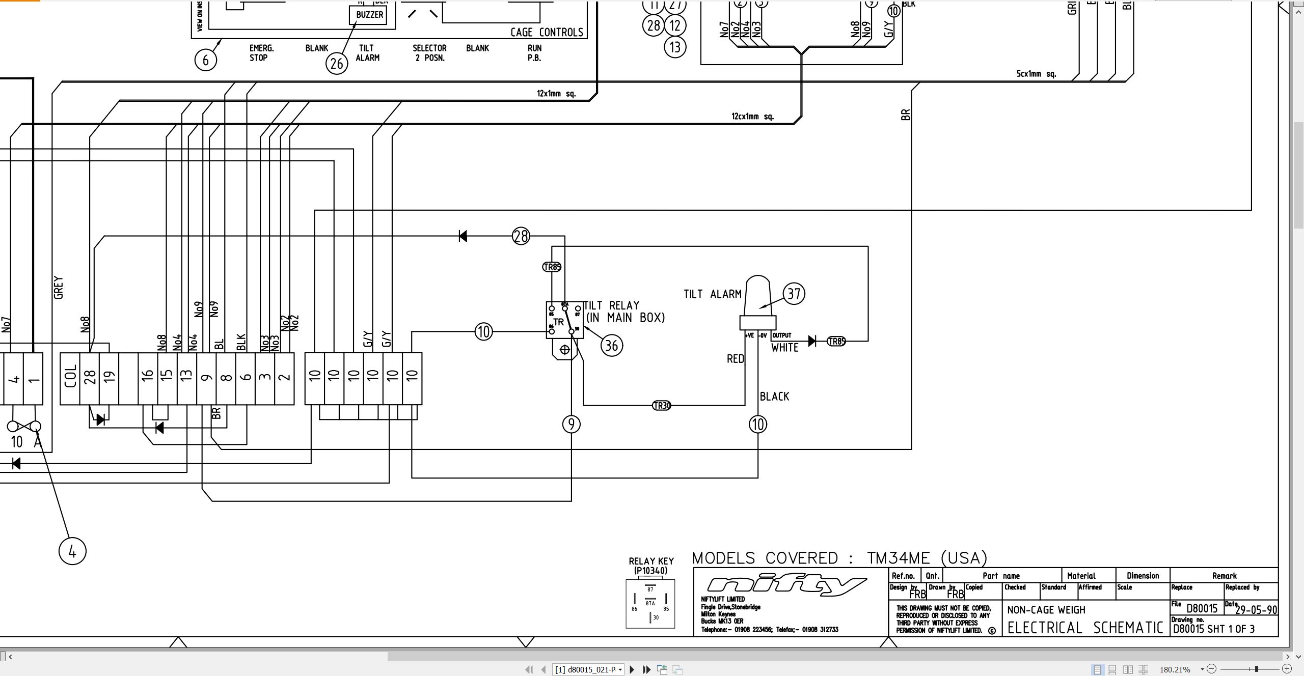
01_SCHEMATIC – ELECTRIC(TM33ME 120ME) D80015 (issue 021) 63370.pdf (3 Pages)
Contents:
Sheets and Views
d80015_021-Pg1
d80015_021-Pg2
d80015_021-BOM
02_WORKING ENVELOPE, 120M D80016 (issue 003) 63370.pdf (2 Pages)
Contents:
Sheets and Views
D80016_003-Metric
D80016_003-Imperial
03_HOSE DIAGRAM 120M D80053 (issue 006) 63370.pdf (1 Pages)
04_LIFTING POINTS, 120M D81193 (issue 004) 63370.pdf (2 Pages)
Contents:
Sheets and Views
D81193_004-English
D81193_004-French
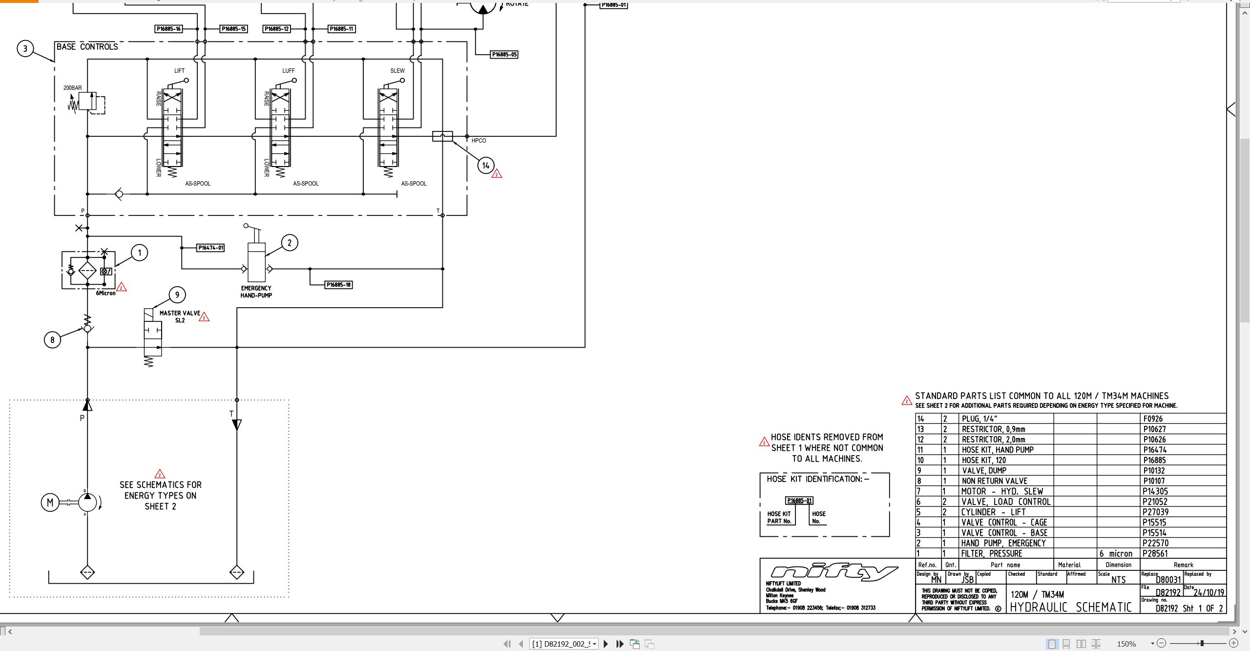
05_120M TM34M Hydraulic Schematic D82192 (issue 002) 63370.pdf (2 Pages)
Contents:
Sheets and Views
D82192_002_Sheet-1
D82192_002_Sheet-2
06_STOWED DIMENSIONS, 120M D82249 (issue 001) 63370.pdf (1 Pages)
Contents:
Sheets and Views
D82249_001-Sheet 1
07_120M TM34M PARTS MANUAL M50111 (issue 020) 63370.pdf (94 Pages)
Contents:
Front Cover
Parts Order Form
chassis assembly
1.1 Base assembly
1.2 Manual jack assembly
1.3 Tow coupling assembly
1.4 Jockey wheel assembly
1.5 Heavy duty jockey wheel
1.6 Lighting assemblies
1.7 Metal Light Support (Options)
1.8 Wheel hub assembly
superstructure
2.1 Power tray (Petrol/Diesel/Bi-energy)
2.2 Power tray (AC/Mains)
2.3 Slew assembly
2.4 Control valve assembly (3 spool)
2.5 Button box assemblies
2.6 Control box
2.7 AC transformer box
2.8 DC Power pack
2.9 AC Power pack
2.10 Diesel engine (Kubota OC60)
2.11 Battery charger
boom assemblies
3.1 Booms assembly
3.2 Lift cylinder
cage assembly
4.1 Cage assembly
4.2 Cage assembly (Fibreglass)
4.3 Cage weigh assembly
4.4 Control valve assembly (3 spool)
4.5 Button box assemblies
labelling
5.1 Label locations 120M
5.2 Label locations TM34M (USA)
Labels 1 – 33
Labels 34 – 47
08_TM34M SERVICE MANUAL – USA M50796 (issue 001) 63370.pdf (61 Pages)
Contents:
1 Introduction and general information
1.1 Foreword
1.1.1 Defined maintenance terms
1.2 Warranty
1.3 Scope
1.4 General maintenance information
1.4.1 Pre-maintenance checks
1.4.2 Maintenance information
1.4.3 Frequent inspection
1.4.4 Annual inspection
1.5 Maintenance safety information
1.5.1 Personal injury prevention
1.5.2 Machine damage prevention
1.5.3 Diesel system safety
1.5.4 Electrical safety
1.5.5 Hydraulic safety
1.5.6 Environmental awareness
2 Specifications
2.1 Engine specifications
2.2 Fluid properties
2.2.1 Fluid volumes
2.2.2 Engine oil specifications
2.2.3 Hydraulic oil specifications
2.2.4 Hydraulic pressure settings
2.3 Tire specifications
2.4 Torque settings
2.4.1 Torque Settings – Kubota OC60 engine
2.5 Hydraulic hose and fitting torque specifications
3 Preventative maintenance
3.1 Maintenance schedules
3.1.1 Engine maintenance
3.1.2 Machine maintenance
3.2 Consumables
3.2.1 Data, safety and specification
3.3 Engine maintenance procedures
3.3.1 Engine oil level check
3.3.2 Engine oil replace
3.3.3 Engine oil strainer – clean
3.3.4 Air filter element maintenance
3.3.5 Fuel tank maintenance
3.3.6 Fuel filter
3.3.7 Fuel injector nozzle
3.3.8 Fuel injection pump
3.3.9 Sediment cup
3.3.10 Fuel hoses
3.3.11 Exhaust system inspect
3.3.12 Valve clearance
3.3.13 Combustion chamber
3.3.14 Spark plug
3.3.15 Spark arrester
3.4 Wheels and tires
3.4.1 Tire condition check
3.4.2 Tire pressure check
3.4.3 Wheel nut torque
3.5 Axle
3.5.1 Axle locating pin inspection and lubricate (monthly)
3.5.2 Axle slides inspection and lubricate (monthly)
3.5.3 Axle inspection (annually)
3.6 Tow coupler
3.7 Braking system
3.7.1 Brake adjustment
3.8 Fenders
3.9 Outriggers
3.9.1 Outrigger inspection and lubricate (monthly)
3.9.2 Manual jack foot plate inspection and lubricate (monthly)
3.10 Hub bearings
3.10.1 Hub bearing check
3.10.2 Hub bearing adjustment
3.10.3 Hub bearing inspection and lubrication
3.11 Lighting
3.11.1 Bulb replacement
3.12 Batteries
3.12.1 Condition check (daily)
3.12.2 Condition check (weekly) – excludes AGM and start battery
3.12.3 Storage
3.13 Hydraulic oil
3.13.1 Level check (weekly)
3.13.2 Pressure filter check (weekly)
3.13.3 Hydraulic oil and filters replace
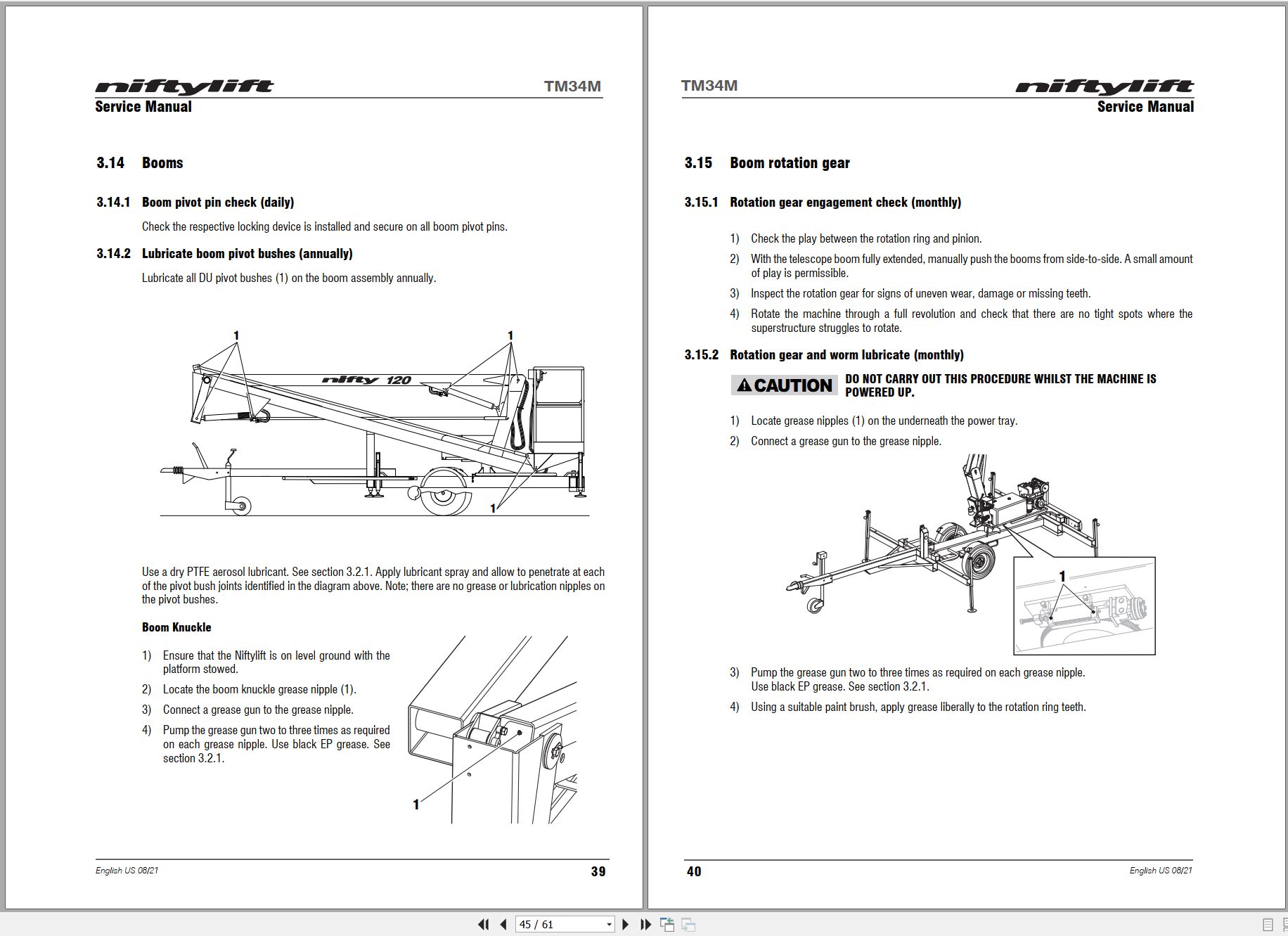
3.14 Booms
3.14.1 Boom pivot pin check (daily)
3.14.2 Lubricate boom pivot bushes (annually)
3.15 Boom rotation gear
3.15.1 Rotation gear engagement check (monthly)
3.15.2 Rotation gear and worm lubricate (monthly)
3.15.3 Center post lubricate (monthly)
3.15.4 Rotation ring bolts check (annually)
4 Repair procedures
4.1 General
4.1.1 Fuses
4.2 Platform/Basket
4.2.1 Footswitch – contact switch replace
4.3 Axle
4.3.1 Brake shoe replacement
5 System overview
5.1 Introduction
5.1.1 Diesel / gasoline system
5.1.2 DC electric system
5.1.3 AC power system
5.1.4 AC/DC power system
5.2 Charging and batteries
5.2.1 Battery charging – extension cords
5.3 Bi-Energy system
5.3.1 Power source selection
5.4 Hydraulic system overview
5.5 Hydraulic pump
5.6 Control logic
6 Troubleshooting guide
6.1 Trouble shooting information
6.2 Platform function fault finding
6.3 Engine fault finding
6.3.1 Diesel engine
6.3.2 Gasoline engine
6.4 Braking system
09_TM34 OPERATING MANUAL (USA) M50900 (issue 004) 63370.pdf (45 Pages)
Contents:
Blank Page
Related Products
-
NIFTYLIFT Towable Boom Lifts TM64 52414 Operating Service Parts Manual And Diagram 2022
40 USDSize: 29.17 MBFormat: PDFLanguage: EnglishBrand: NIFTYLIFTType of Machine: Towable Boom LiftsType of Manual: Service Manual, Operating Manual, Parts Manual, Electrical Schematic, Hydraulic Schematic,Model: NIFTYLIFT TM64 Towable Boom LiftsSerial Number: 52414Publication Date: 2022
REALEASE :
REALEASE :
-
NIFTYLIFT Towable Boom Lifts TM50 56687 Operating Service Parts Manual And Diagram 2025
50 USDSize: 20.05 MBFormat: PDFLanguage: EnglishBrand: NIFTYLIFTType of Machine: Towable Boom LiftsType of Manual: Service Manual, Operating Manual, Parts Manual, Electrical Schematic, Hydraulic Schematic,Model: NIFTYLIFT TM50 Towable Boom LiftsSerial Number: 56687Publication Date: 2025
REALEASE :
REALEASE :
-
NIFTYLIFT Towable Boom Lifts TM64 55045 Operators Service Manual Diagram 2023
40 USDSize: 28.66 MBFormat: PDFLanguage: EnglishBrand: NIFTYLIFTType of Machine: Towable Boom LiftsType of Manual: Service Manual, Operating Manual, Parts Manual, Electrical SchematicModel: NIFTYLIFT TM64 Towable Boom LiftsSerial Number: 55045Publication Date: 2023
REALEASE :
REALEASE :
-
NIFTYLIFT Towable Boom Lifts TM50 57219 Operating Service Parts Manual And Diagram 2025
50 USDSize: 27.83 MBFormat: PDFLanguage: EnglishBrand: NIFTYLIFTType of Machine: Towable Boom LiftsType of Manual: Service Manual, Operating Manual, Parts Manual, Electrical Schematic, Hydraulic Schematic,Model: NIFTYLIFT TM50 Towable Boom LiftsSerial Number: 57219Publication Date: 2025
REALEASE :
REALEASE :
-
NIFTYLIFT Towable Boom Lifts TM64 55060 Operating Service Parts Manual And Diagram 2023
40 USDSize: 28.83 MBFormat: PDFLanguage: EnglishBrand: NIFTYLIFTType of Machine: Towable Boom LiftsType of Manual: Service Manual, Operating Manual, Parts Manual, Electrical Schematic, Hydraulic Schematic,Model: NIFTYLIFT TM64 Towable Boom LiftsSerial Number: 55060Publication Date: 2023
REALEASE :
REALEASE :
-
NIFTYLIFT Towable Boom Lifts TM50 58728 Operating Service Parts Manual And Diagram 2025
50 USDSize: 20.05 MBFormat: PDFLanguage: EnglishBrand: NIFTYLIFTType of Machine: Towable Boom LiftsType of Manual: Service Manual, Operating Manual, Parts Manual, Electrical Schematic, Hydraulic Schematic,Model: NIFTYLIFT TM50 Towable Boom LiftsSerial Number: 58728Publication Date: 2025
REALEASE :
REALEASE :
-
NIFTYLIFT Towable Boom Lifts TM50 56720 Operating Service Parts Manual And Diagram 2025
50 USDSize: 27.98 MBFormat: PDFLanguage: EnglishBrand: NIFTYLIFTType of Machine: Towable Boom LiftsType of Manual: Service Manual, Operating Manual, Parts Manual, Electrical Schematic, Hydraulic Schematic,Model: NIFTYLIFT TM50 Towable Boom LiftsSerial Number: 56720Publication Date: 2025
REALEASE :
REALEASE :
-
NIFTYLIFT Towable Boom Lifts TM64 56064 Operating Service Parts Manual And Diagram 2023
40 USDSize: 28.80 MBFormat: PDFLanguage: EnglishBrand: NIFTYLIFTType of Machine: Towable Boom LiftsType of Manual: Service Manual, Operating Manual, Inspection Manual, Parts Manual, Electrical Schematic, Hydraulic Schematic,Model: NIFTYLIFT TM64 Towable Boom LiftsSerial Number: 56064Publication Date: 2023
REALEASE :
REALEASE :