
0 ITEMSVIEW CART

✓
Expert Support
✓
Full Speed
✓
100% Working
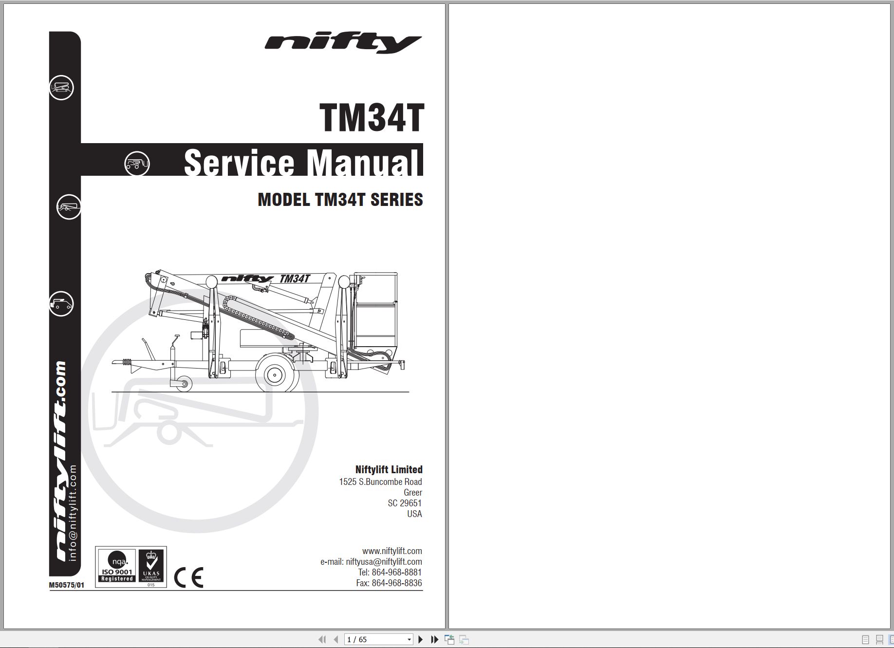
NIFTYLIFT Towable Boom Lifts TM34T 52618 Operating Service Parts Manual And Diagram 2023
Size: 15.28 MB
Format: PDF
Language: English
Brand: NIFTYLIFT
Type of Machine: Towable Boom Lifts
Type of Manual: Service Manual, Operating Manual, Parts Manual, Electrical Schematic, Hydraulic Schematic, Hose Diagram
Model: NIFTYLIFT TM34T Towable Boom Lifts
Serial Number: 52618
Publication Date: 2023
40 USD
- Description
Description
List of Files:
01_HOSE DIAGRAM 120T INSTINCTIVE D80280 (issue 005) 52618.pdf (1 Pages)
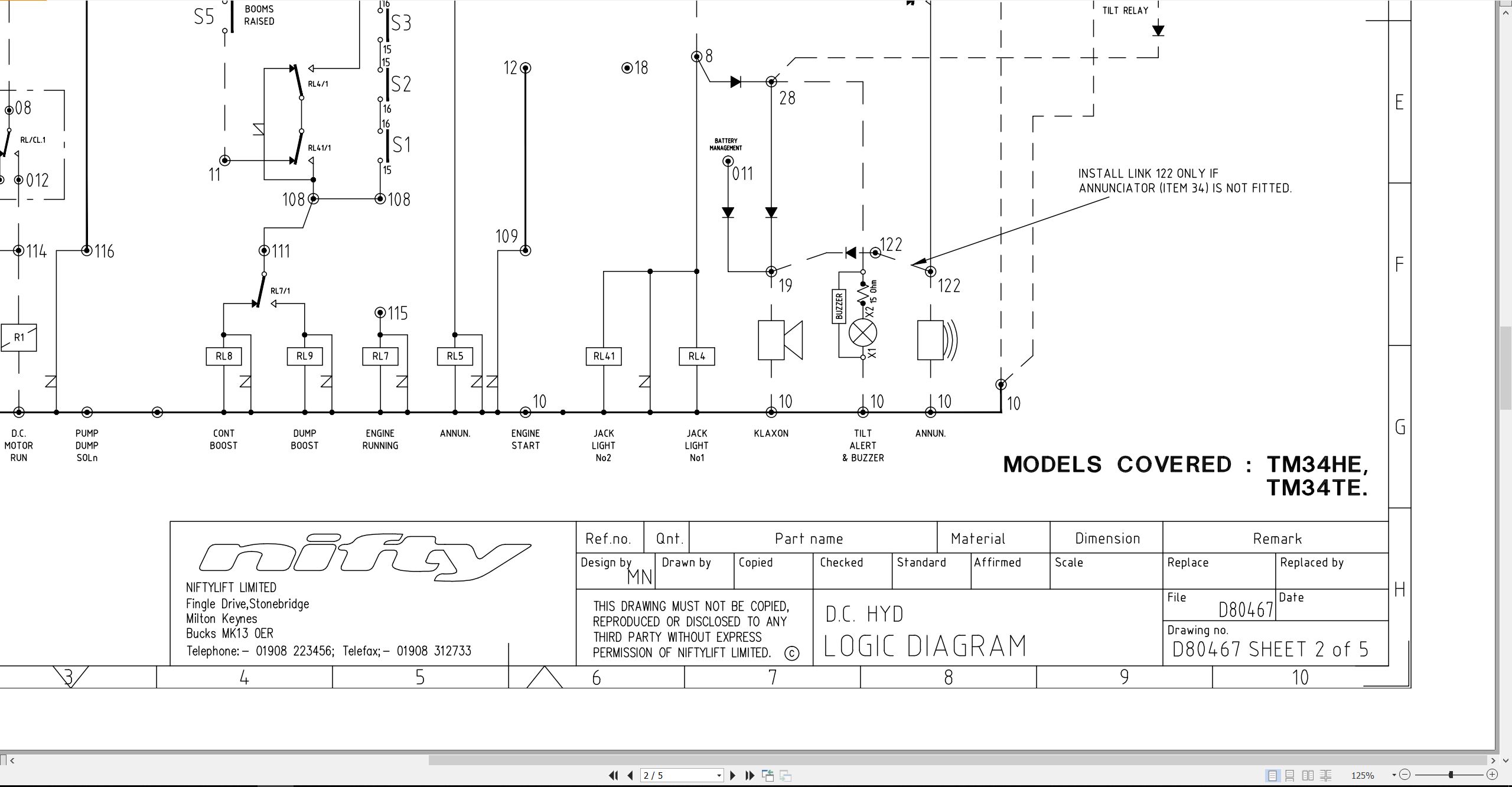
02_ELECTRICAL SCHEMATIC USA 120TE HE D80467 (issue 020) 52618.pdf (5 Pages)
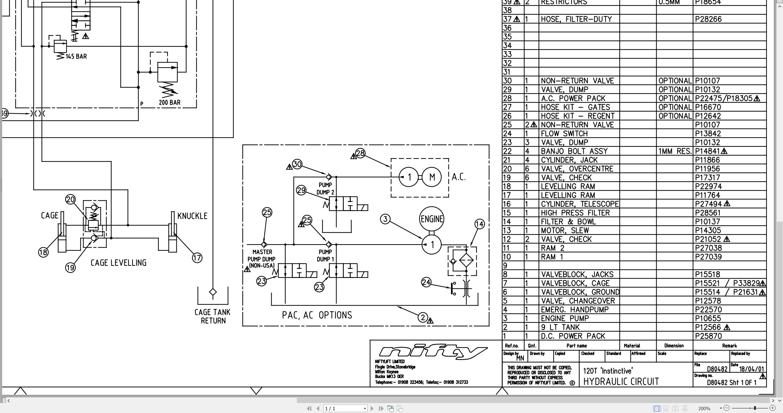
03_HYDRAULIC DIAGRAM 120T INST D80482 (issue 009) 52618.pdf (1 Pages)
04_LIFTING POINTS, 120T D80541 (issue 005) 52618.pdf (2 Pages)
05_120T TM34T PARTS MANUAL M50120 (issue 021) 52618.pdf (122 Pages)
Contents:
chassis assembly
1.1 Base assembly – Sliding axle
1.2 Base assembly – Fixed axle
1.3 Traction drive assembly
1.4 Stabiliser assembly
1.5 Tow coupling assembly
1.6 Jockey wheel assembly
1.7 Heavy duty jockey wheel
1.8 Lighting assemblies
1.9 Wheel hub assembly
1.10 Valve block (Traction drive)
superstructure
2.1 Power tray (P/D/E/PE)
2.2 Power tray (AC/DC)
2.3 Power tray (AC)
2.4 Power tray (DC – Lithium)
2.5 Slew assembly
2.6 Control valve assembly (3 spool)
2.7 Control valve assembly (4 spool)
2.8 Button box assemblies
2.9 PCB Control box
2.10 AC transformer box
2.11 AC/DC transformer box
2.12 DC Power pack
2.13 AC Power pack
2.14 DC Power pack (AC/DC machine)
2.15 Battery charger (UK)
2.16 Battery charger (Euro/Australia & USA)
boom assemblies
3.1 Booms assembly
3.2 Lift cylinder
3.3 Levelling cylinder
3.4 Telescope cylinder
3.5 Energy chain
cage assembly
4.1 Cage assembly
4.2 Cage assembly (Fibreglass)
4.3 Cage weigh assembly
4.4 Control valve assembly (Cage)
4.5 Button box assemblies
labelling
5.1 Label locations
Figure 5.1
Labels 1 to 33
Labels 34 to 54
hydraulic hoses
6.1 Hose kit 120T (TM34T)
6.2 Traction Drive Kit (P14205)
06_TM34T SERVICE MANUAL M50575 (issue 001) 52618.pdf (65 Pages)
Contents:
1 Introduction and general information
1.1 Foreword
1.1.1 Defined maintenance terms
1.2 Warranty
1.3 Scope
1.4 General maintenance information
1.4.1 Pre-maintenance checks
1.4.2 Maintenance information
1.4.3 Frequent inspection
1.4.4 Annual inspection
1.5 Maintenance safety information
1.5.1 Personal injury prevention
1.5.2 Machine damage prevention
1.5.3 Diesel system safety
1.5.4 Electrical safety
1.5.5 Hydraulic safety
1.5.6 Environmental awareness
2 Specifications
2.1 Engine specifications
2.2 Fluid properties
2.2.1 Fluid volumes
2.2.2 Engine oil specifications
2.2.3 Hydraulic oil specifications
2.2.4 Hydraulic pressure settings
2.3 Tire specifications
2.4 Torque settings
2.5 Hydraulic hose and fitting torque specifications
3 Preventative maintenance
3.1 Maintenance schedules
3.1.1 Engine maintenance
3.1.2 Machine maintenance
3.2 Consumables
3.2.1 Data, safety and specification
3.3 Engine maintenance procedures
3.3.1 Engine oil level check
3.3.2 Engine oil replace
3.3.3 Engine oil filter replace
3.3.4 Air filter element maintenance
3.3.5 Fuel filter and fuel tank maintenance
3.3.6 Fuel injector nozzle
3.3.7 Sediment cup
3.3.8 Cylinder compression
3.3.9 Fuel hoses
3.3.10 Exhaust system inspect
3.3.11 Valve clearance
3.3.12 Combustion chamber
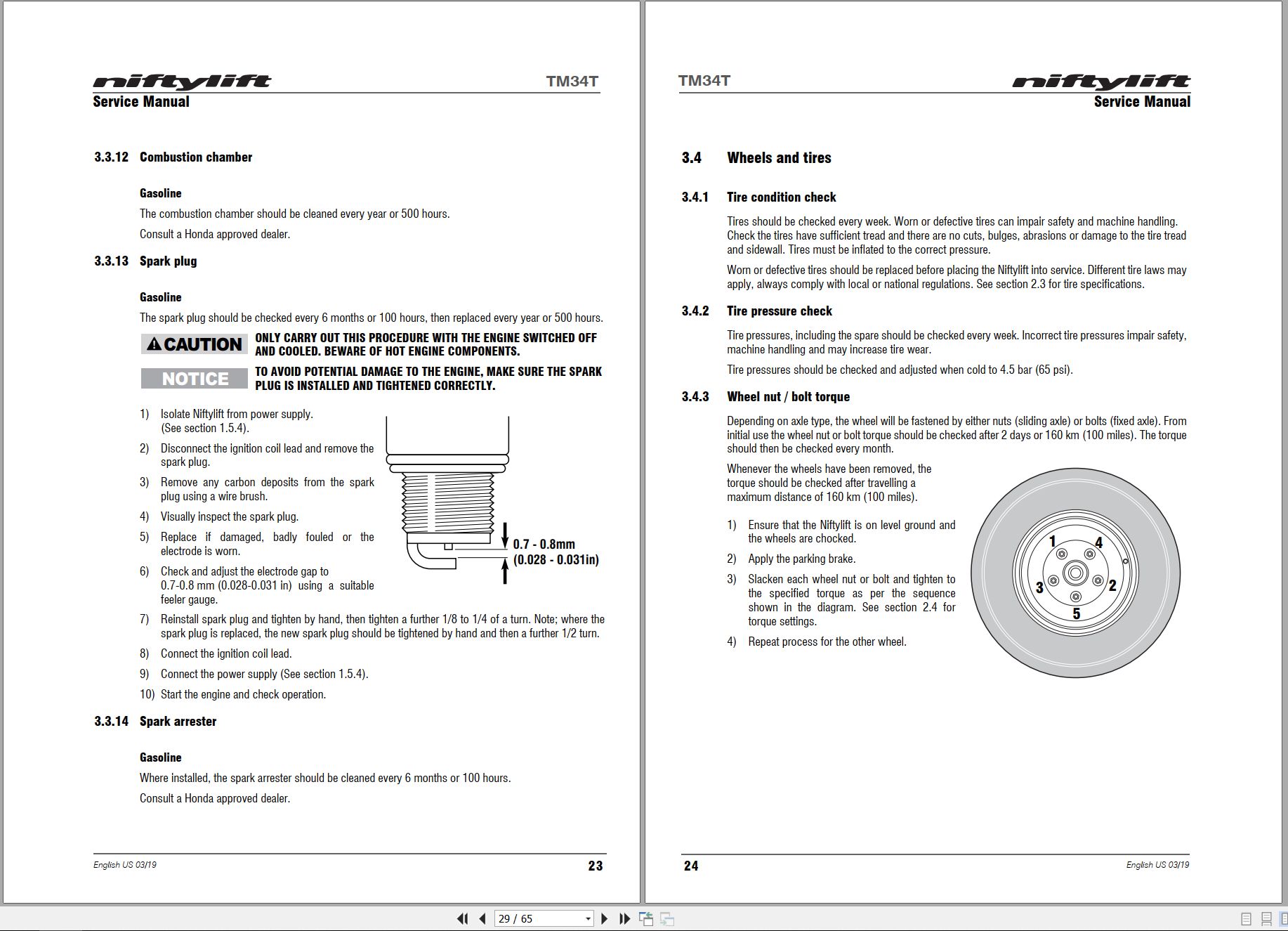
3.3.13 Spark plug
3.3.14 Spark arrester
3.4 Wheels and tires
3.4.1 Tire condition check
3.4.2 Tire pressure check
3.4.3 Wheel nut / bolt torque
3.5 Axle suspension
3.5.1 Axle inspection
3.6 Traction drive
3.7 Tow coupler
3.8 Braking system
3.8.1 Brake adjustment
3.9 Fenders
3.10 Stabilizers
3.10.1 Stabilizer foot plate inspection and lubricate (monthly)
3.10.2 Stabilizer pivot pins
3.11 Hub bearings
3.11.1 Hub bearing check
3.11.2 Hub bearing adjustment
3.11.3 Hub bearing inspection and lubrication
3.12 Lighting
3.12.1 Bulb replacement
3.13 Batteries
3.13.1 Condition check (daily)
3.13.2 Condition check (weekly) – excludes AGM & Li-ion batteries
3.13.3 Storage
3.14 Hydraulic oil
3.14.1 Level check (weekly)
3.14.2 Pressure filter check (weekly)
3.14.3 Hydraulic oil and filters replace
3.15 Telescopic boom
3.15.1 Wear pad check & lubricate (monthly)
3.15.2 Hose trunking and energy chain check (weekly)
3.15.3 Boom pivot pin check (daily)
3.15.4 Lubricate boom pivot bushes (annually)
3.16 Boom rotation gear
3.16.1 Rotation gear engagement check (monthly)
3.16.2 Rotation ring (monthly)
3.16.3 Rotation ring bolts check (annually)
4 Repair procedures
4.1 General
4.1.1 Fuses
4.2 Platform/Basket
4.2.1 Footswitch – contact switch replace
4.3 Booms
4.3.1 Energy chain link
4.4 Base assembly
4.4.1 Stabilizer microswitch
4.5 Axle
4.5.1 Brake shoe replacement
5 System overview
5.1 Introduction
5.1.1 Diesel / gasoline system
5.1.2 DC electric system
5.1.3 AC power system
5.1.4 AC/DC power system
5.2 Charging and batteries
5.2.1 Battery charging – extension cords
5.3 Bi-Energy system
5.3.1 Duty selector
5.4 Boom system
5.4.1 Boom switch
5.5 Hydraulic system overview
5.6 Hydraulic pump
5.7 Control logic
6 Troubleshooting guide
6.1 Trouble shooting information
6.2 Platform function fault finding
6.3 Engine fault finding
6.3.1 Diesel engine
6.3.2 Gasoline engine
6.4 Li-ion battery system
6.5 Braking system
07_TM34T OPERATING MANUAL (USA) M50901 (issue 001) 52618.pdf (38 Pages)
Related Products
-
NIFTYLIFT Towable Boom Lifts TM64 55060 Operating Service Parts Manual And Diagram 2023
40 USDSize: 28.83 MBFormat: PDFLanguage: EnglishBrand: NIFTYLIFTType of Machine: Towable Boom LiftsType of Manual: Service Manual, Operating Manual, Parts Manual, Electrical Schematic, Hydraulic Schematic,Model: NIFTYLIFT TM64 Towable Boom LiftsSerial Number: 55060Publication Date: 2023
REALEASE :
REALEASE :
-
NIFTYLIFT Towable Boom Lifts TM64 56064 Operating Service Parts Manual And Diagram 2023
40 USDSize: 28.80 MBFormat: PDFLanguage: EnglishBrand: NIFTYLIFTType of Machine: Towable Boom LiftsType of Manual: Service Manual, Operating Manual, Inspection Manual, Parts Manual, Electrical Schematic, Hydraulic Schematic,Model: NIFTYLIFT TM64 Towable Boom LiftsSerial Number: 56064Publication Date: 2023
REALEASE :
REALEASE :
-
NIFTYLIFT Towable Boom Lifts TM50 56687 Operating Service Parts Manual And Diagram 2025
50 USDSize: 20.05 MBFormat: PDFLanguage: EnglishBrand: NIFTYLIFTType of Machine: Towable Boom LiftsType of Manual: Service Manual, Operating Manual, Parts Manual, Electrical Schematic, Hydraulic Schematic,Model: NIFTYLIFT TM50 Towable Boom LiftsSerial Number: 56687Publication Date: 2025
REALEASE :
REALEASE :
-
NIFTYLIFT Towable Boom Lifts TM64 55045 Operators Service Manual Diagram 2023
40 USDSize: 28.66 MBFormat: PDFLanguage: EnglishBrand: NIFTYLIFTType of Machine: Towable Boom LiftsType of Manual: Service Manual, Operating Manual, Parts Manual, Electrical SchematicModel: NIFTYLIFT TM64 Towable Boom LiftsSerial Number: 55045Publication Date: 2023
REALEASE :
REALEASE :
-
NIFTYLIFT Towable Boom Lifts TM50 57219 Operating Service Parts Manual And Diagram 2025
50 USDSize: 27.83 MBFormat: PDFLanguage: EnglishBrand: NIFTYLIFTType of Machine: Towable Boom LiftsType of Manual: Service Manual, Operating Manual, Parts Manual, Electrical Schematic, Hydraulic Schematic,Model: NIFTYLIFT TM50 Towable Boom LiftsSerial Number: 57219Publication Date: 2025
REALEASE :
REALEASE :
-
NIFTYLIFT Towable Boom Lifts TM64 52414 Operating Service Parts Manual And Diagram 2022
40 USDSize: 29.17 MBFormat: PDFLanguage: EnglishBrand: NIFTYLIFTType of Machine: Towable Boom LiftsType of Manual: Service Manual, Operating Manual, Parts Manual, Electrical Schematic, Hydraulic Schematic,Model: NIFTYLIFT TM64 Towable Boom LiftsSerial Number: 52414Publication Date: 2022
REALEASE :
REALEASE :
-
NIFTYLIFT Towable Boom Lifts TM50 56720 Operating Service Parts Manual And Diagram 2025
50 USDSize: 27.98 MBFormat: PDFLanguage: EnglishBrand: NIFTYLIFTType of Machine: Towable Boom LiftsType of Manual: Service Manual, Operating Manual, Parts Manual, Electrical Schematic, Hydraulic Schematic,Model: NIFTYLIFT TM50 Towable Boom LiftsSerial Number: 56720Publication Date: 2025
REALEASE :
REALEASE :
-
NIFTYLIFT Towable Boom Lifts TM50 58728 Operating Service Parts Manual And Diagram 2025
50 USDSize: 20.05 MBFormat: PDFLanguage: EnglishBrand: NIFTYLIFTType of Machine: Towable Boom LiftsType of Manual: Service Manual, Operating Manual, Parts Manual, Electrical Schematic, Hydraulic Schematic,Model: NIFTYLIFT TM50 Towable Boom LiftsSerial Number: 58728Publication Date: 2025
REALEASE :
REALEASE :