")


Expert Support
Full Speed
100% Working
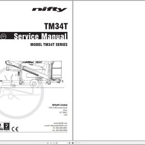
NIFTYLIFT Towable Boom Lifts TM34T 59293 Operating Service Parts Manual And Diagram 2024
40 USD
- Description
Description
List of Files:
01_WORKING ENVELOPE, 120T D80227 (issue 003) 59293.pdf (1 Pages)
02_HOSE DIAGRAM 120T INSTINCTIVE D80280 (issue 005) 59293.pdf (1 Pages)
03_ELEC DRG 120H TPE INSTINCT D80468 (issue 023) 59293.pdf (5 Pages)
04_HYDRAULIC DIAGRAM 120T INST D80482 (issue 009) 59293.pdf (1 Pages)
05_120T TM34T PARTS MANUAL M50120 (issue 030) 59293.pdf (126 Pages)
Contents:
Introduction
Parts Order Form
Contents
chassis assembly
1.1 Base assembly – Sliding axle
1.2 Base assembly – Fixed axle
1.3 Traction drive assembly
1.4 Stabiliser assembly
1.5 Tow coupling assembly
1.6 Jockey wheel assembly
1.7 Heavy duty jockey wheel
1.8 Lighting assemblies
1.9 Wheel hub assembly
1.10 Valve block (Traction drive)
superstructure
2.1 Power tray (P/D/E/PE)
2.2 Power tray (AC/DC)
2.3 Power tray (AC)
2.4 Power tray (DC – Lithium)
2.5 Slew assembly
2.6 Control valve assembly (3 spool)
2.7 Control valve assembly (4 spool)
2.8 Button box assemblies
2.9 PCB Control box
2.10 AC transformer box
2.11 AC/DC transformer box
2.12 DC Power pack
2.13 AC Power pack
2.14 DC Power pack (AC/DC machine)
2.15 Battery charger (UK)
2.16 Battery charger (Euro/Australia & USA)
boom assemblies
3.1 Booms assembly
3.2 Lift cylinder
3.3 Levelling cylinder
3.4 Telescope cylinder
3.5 Energy chain
cage assembly
4.1 Cage assembly
4.2 Cage assembly (Fibreglass)
4.3 Cage weigh assembly
4.4 Control valve assembly (Cage)
4.5 Button box assemblies
labelling
5.1 Label locations
Figure 5.1
Labels 1 to 33
Labels 34 to 54
hydraulic hoses
6.1 Hose kit 120T (TM34T)
6.2 Traction Drive Kit (P14205)
06_Honda GX160 Operators Manual M50294 (issue 001) 59293.pdf (60 Pages)
Contents:
INTRODUCTION
SAFETY MESSAGES
CONTENTS
SAFETY INFORMATION
SAFETY LABEL LOCATION
COMPONENT & CONTROL LOCATION
FEATURES
OIL ALERT® SYSTEM (APPLICABLE TYPES)
CIRCUIT PROTECTOR (APPLICABLE TYPES)
BEFORE OPERATION CHECKS
IS YOUR ENGINE READY TO GO?
OPERATION
SAFE OPERATING PRECAUTIONS
STARTING THE ENGINE
STOPPING THE ENGINE
SETTING ENGINE SPEED
SERVICING YOUR ENGINE
THE IMPORTANCE OF MAINTENANCE
MAINTENANCE SAFETY
SAFETY PRECAUTIONS
MAINTENANCE SCHEDULE
REFUELING
RECOMMENDED FUEL
ENGINE OIL
RECOMMENDED OIL
OIL LEVEL CHECK
OIL CHANGE
REDUCTION CASE OIL (APPLICABLE TYPES)
RECOMMENDED OIL
OIL LEVEL CHECK
OIL CHANGE
AIR CLEANER
INSPECTION
CLEANING
SEDIMENT CUP
CLEANING
SPARK PLUG
RECOMMENDED SPARK PLUGS
SPARK ARRESTER (APPLICABLE TYPES)
REMOVAL
CLEANING & INSPECTION
IDLE SPEED
ADJUSTMENT
HELPFUL TIPS & SUGGESTIONS
STORING YOUR ENGINE
STORAGE PREPARATION
CLEANING
FUEL
DRAINING THE FUEL TANK AND CARBURETOR
ENGINE OIL
STORAGE PRECAUTIONS
REMOVAL FROM STORAGE
TRANSPORTING
TAKING CARE OF UNEXPECTED PROBLEMS
FUSE REPLACEMENT (APPLICABLE TYPES)
TECHNICAL & CONSUMER INFORMATION
TECHNICAL INFORMATION
SERIAL NUMBER LOCATION
BATTERY CONNECTIONS FOR ELECTRIC STARTER (APPLICABLE TYPES)
REMOTE CONTROL LINKAGE
CARBURETOR MODIFICATIONS FOR HIGH ALTITUDE OPERATION
OXYGENATED FUELS
EMISSION CONTROL SYSTEM INFORMATION
AIR INDEX
SPECIFICATIONS
QUICK REFERENCE INFORMATION
WIRING DIAGRAMS
CONSUMER INFORMATION
DISTRIBUTOR/DEALER LOCATOR INFORMATION
CUSTOMER SERVICE INFORMATION
FRANÇAIS
ESPAÑOL
07_TM34T SERVICE MANUAL M50575 (issue 001) 59293.pdf (65 Pages)
Contents:
1 Introduction and general information
1.1 Foreword
1.1.1 Defined maintenance terms
1.2 Warranty
1.3 Scope
1.4 General maintenance information
1.4.1 Pre-maintenance checks
1.4.2 Maintenance information
1.4.3 Frequent inspection
1.4.4 Annual inspection
1.5 Maintenance safety information
1.5.1 Personal injury prevention
1.5.2 Machine damage prevention
1.5.3 Diesel system safety
1.5.4 Electrical safety
1.5.5 Hydraulic safety
1.5.6 Environmental awareness
2 Specifications
2.1 Engine specifications
2.2 Fluid properties
2.2.1 Fluid volumes
2.2.2 Engine oil specifications
2.2.3 Hydraulic oil specifications
2.2.4 Hydraulic pressure settings
2.3 Tire specifications
2.4 Torque settings
2.5 Hydraulic hose and fitting torque specifications
3 Preventative maintenance
3.1 Maintenance schedules
3.1.1 Engine maintenance
3.1.2 Machine maintenance
3.2 Consumables
3.2.1 Data, safety and specification
3.3 Engine maintenance procedures
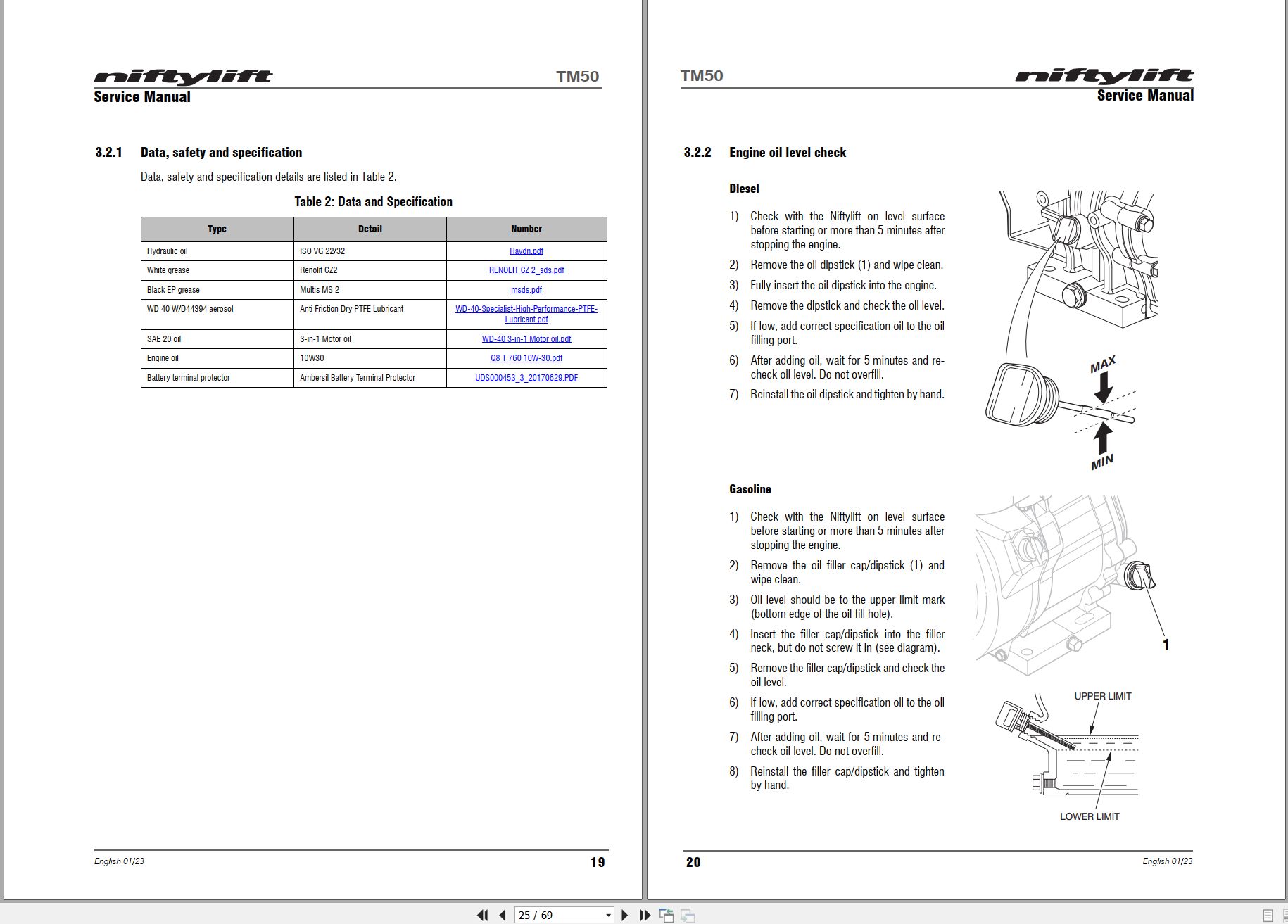
3.3.1 Engine oil level check
3.3.2 Engine oil replace
3.3.3 Engine oil filter replace
3.3.4 Air filter element maintenance
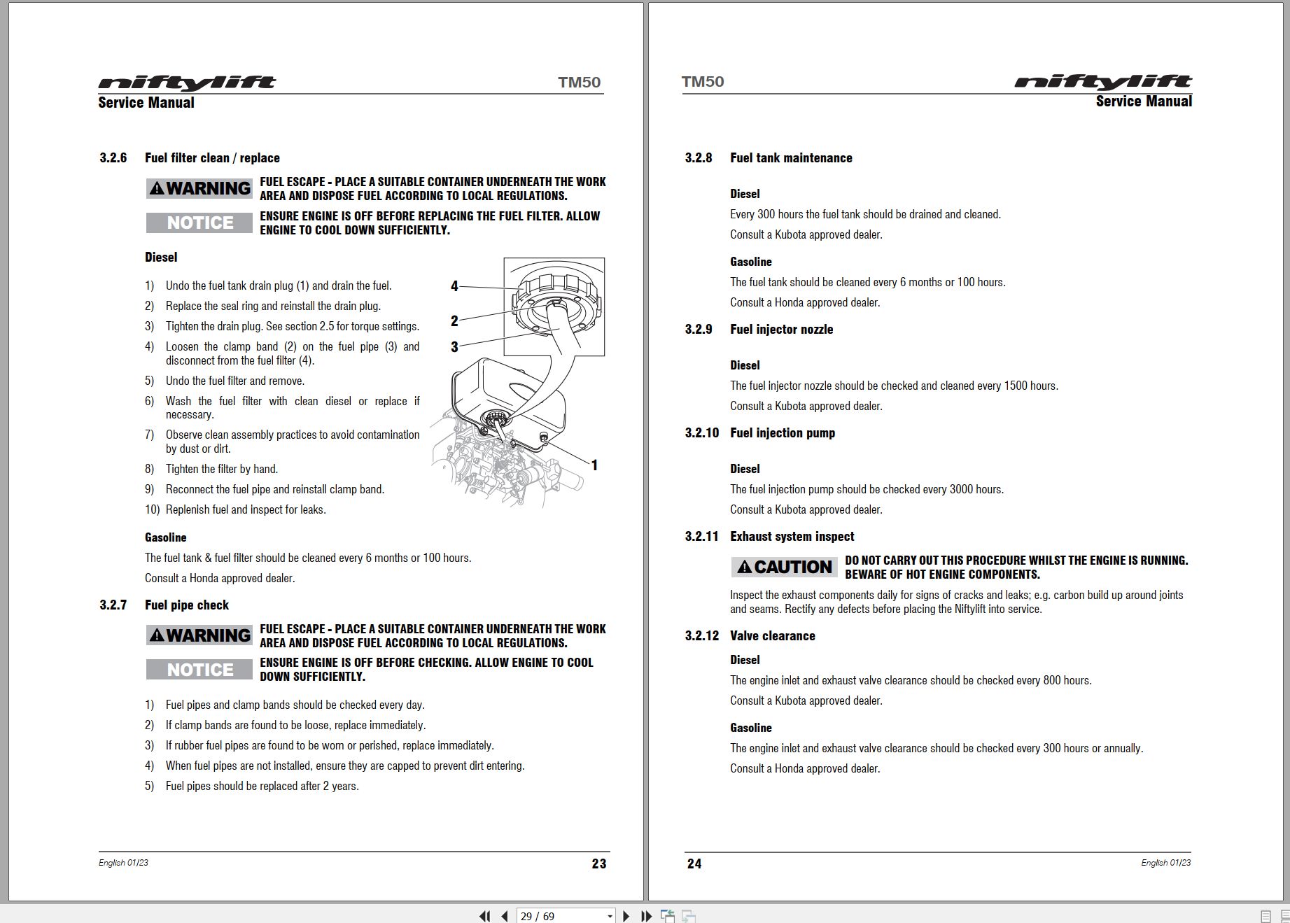
3.3.5 Fuel filter and fuel tank maintenance
3.3.6 Fuel injector nozzle
3.3.7 Sediment cup
3.3.8 Cylinder compression
3.3.9 Fuel hoses
3.3.10 Exhaust system inspect
3.3.11 Valve clearance
3.3.12 Combustion chamber
3.3.13 Spark plug
3.3.14 Spark arrester
3.4 Wheels and tires
3.4.1 Tire condition check
3.4.2 Tire pressure check
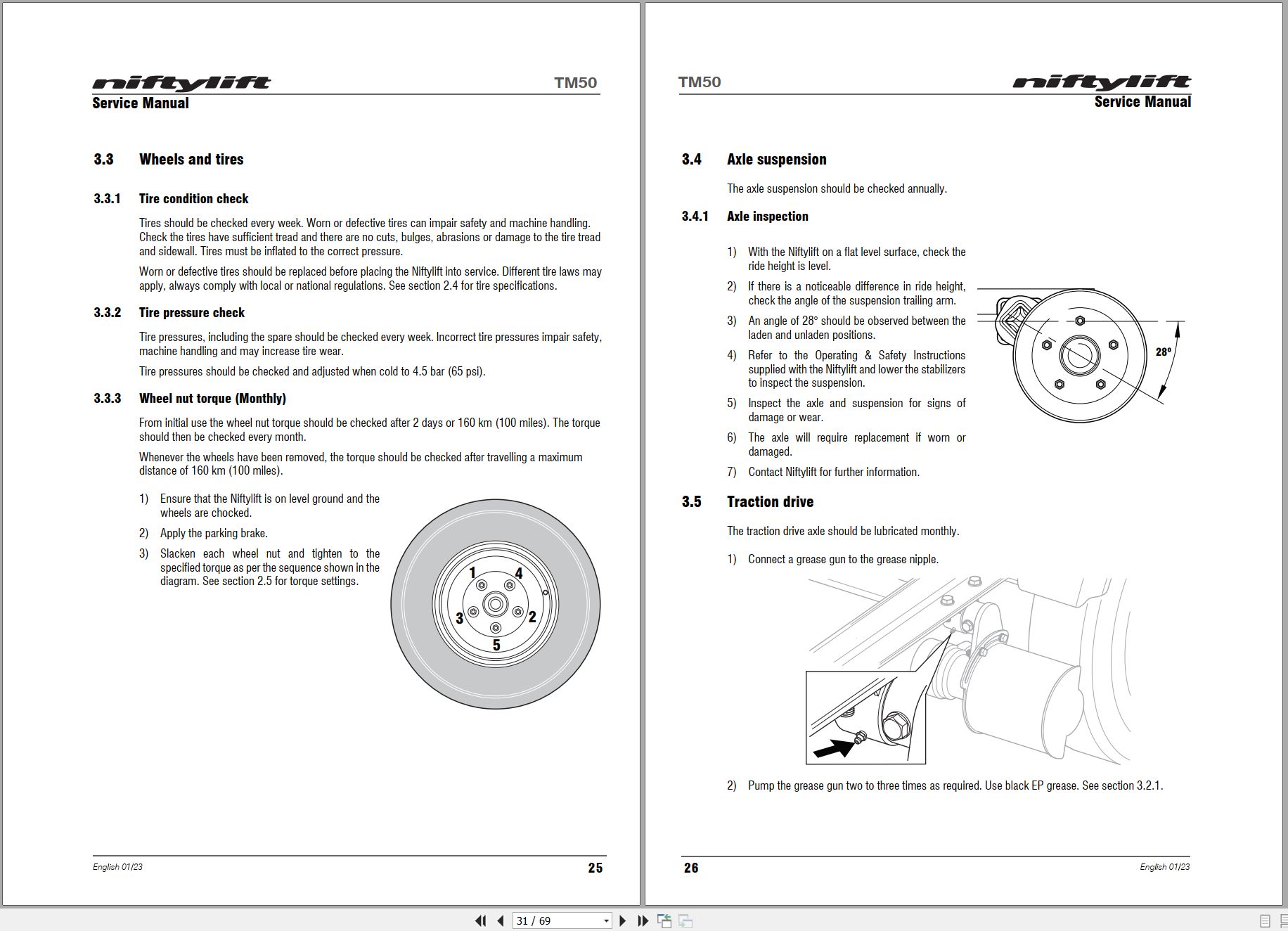
3.4.3 Wheel nut / bolt torque
3.5 Axle suspension
3.5.1 Axle inspection
3.6 Traction drive
3.7 Tow coupler
3.8 Braking system
3.8.1 Brake adjustment
3.9 Fenders
3.10 Stabilizers
3.10.1 Stabilizer foot plate inspection and lubricate (monthly)
3.10.2 Stabilizer pivot pins
3.11 Hub bearings
3.11.1 Hub bearing check
3.11.2 Hub bearing adjustment
3.11.3 Hub bearing inspection and lubrication
3.12 Lighting
3.12.1 Bulb replacement
3.13 Batteries
3.13.1 Condition check (daily)
3.13.2 Condition check (weekly) – excludes AGM & Li-ion batteries
3.13.3 Storage
3.14 Hydraulic oil
3.14.1 Level check (weekly)
3.14.2 Pressure filter check (weekly)
3.14.3 Hydraulic oil and filters replace
3.15 Telescopic boom
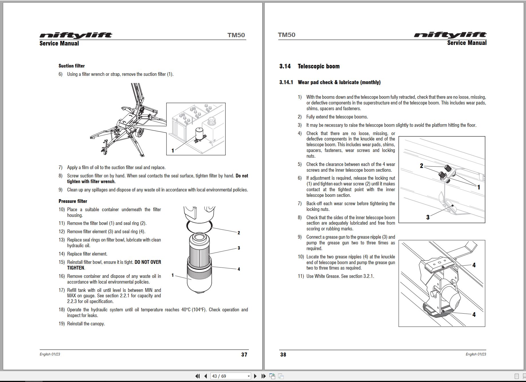
3.15.1 Wear pad check & lubricate (monthly)
3.15.2 Hose trunking and energy chain check (weekly)
3.15.3 Boom pivot pin check (daily)
3.15.4 Lubricate boom pivot bushes (annually)
3.16 Boom rotation gear
3.16.1 Rotation gear engagement check (monthly)
3.16.2 Rotation ring (monthly)
3.16.3 Rotation ring bolts check (annually)
4 Repair procedures
4.1 General
4.1.1 Fuses
4.2 Platform/Basket
4.2.1 Footswitch – contact switch replace
4.3 Booms
4.3.1 Energy chain link
4.4 Base assembly
4.4.1 Stabilizer microswitch
4.5 Axle
4.5.1 Brake shoe replacement
5 System overview
5.1 Introduction
5.1.1 Diesel / gasoline system
5.1.2 DC electric system
5.1.3 AC power system
5.1.4 AC/DC power system
5.2 Charging and batteries
5.2.1 Battery charging – extension cords
5.3 Bi-Energy system
5.3.1 Duty selector
5.4 Boom system
5.4.1 Boom switch
5.5 Hydraulic system overview
5.6 Hydraulic pump
5.7 Control logic
6 Troubleshooting guide
6.1 Trouble shooting information
6.2 Platform function fault finding
6.3 Engine fault finding
6.3.1 Diesel engine
6.3.2 Gasoline engine
6.4 Li-ion battery system
6.5 Braking system
08_TM34T OPERATING MANUAL (USA) M50901 (issue 006) 59293.pdf (41 Pages)
Related Products
-
NIFTYLIFT Towable Boom Lifts TM64 56064 Operating Service Parts Manual And Diagram 2023
40 USD -
NIFTYLIFT Towable Boom Lifts TM64 55045 Operators Service Manual Diagram 2023
40 USD -
NIFTYLIFT Towable Boom Lifts TM50 56687 Operating Service Parts Manual And Diagram 2025
50 USD -
NIFTYLIFT Towable Boom Lifts TM64 55060 Operating Service Parts Manual And Diagram 2023
40 USD -
NIFTYLIFT Towable Boom Lifts TM50 57219 Operating Service Parts Manual And Diagram 2025
50 USD -
NIFTYLIFT Towable Boom Lifts TM64 52414 Operating Service Parts Manual And Diagram 2022
40 USD -
NIFTYLIFT Towable Boom Lifts TM50 58728 Operating Service Parts Manual And Diagram 2025
50 USD -
NIFTYLIFT Towable Boom Lifts TM50 56720 Operating Service Parts Manual And Diagram 2025
50 USD