

Expert Support
Full Speed
100% Working
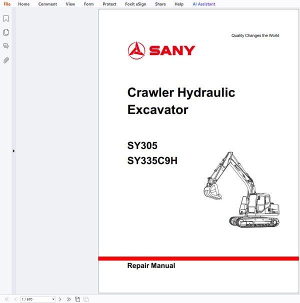
Sany Excavator SY305 SY335C9H Schematics Repair Manual
30 USD
- Description
Description
Contents:
1 Introduction
1.1 How to Read the Shop Manual
1.1.1 Foreword
1.1.2 Manual organization
1.1.3 Units
1.1.4 Revision and publication
1.1.5 Symbols
1.2 Technical Terms for Maintenance Standard
1.3 Handling Electrical or Hydraulic Components
1.3.1 Foreword
1.3.2 Precautions for handling electrical components
1.3.3 Precautions for handling hydraulic components
1.4 Hose Joint
1.4.1 Foreword
1.4.2 Type of hose joint
1.4.3 Hose joint tightening torque table
1.4.4 Connection of O-rings
1.5 Standard Tightening Torque Table
1.6 Type of Bolts
1.7 Tightening Sequence
1.8 Maintenance of Split Flanges
1.9 Conversion Tables
1.9.1 Foreword
1.9.2 Length
1.9.3 Area
1.9.4 Volume
1.9.5 Mass
1.9.6 Pressure
1.9.7 Tightening Torque
1.9.8 Temperature
2 Shop Safety
2.1 Hazard Alert Information
2.2 General Shop Safety
2.2.1 Foreword
2.2.2 Rules and shop behavior
2.2.3 Housekeeping
2.2.4 Shop Liquids Storage
2.2.5 Cleaning Parts
2.2.6 Jacking Up the Machine
2.2.7 Electrical Dangers
2.2.8 Removing Attachments
2.2.9 Cleaning the Machine
2.2.10 Using the Correct Tools
2.2.11 Hoisting a Load
2.2.12 Appropriate Working Apparel
2.2.13 Safety Partners
2.2.14 Two people when engine running
2.2.15 Driving Pins
2.2.16 Aligning Parts or Components
2.2.17 Fire Extinguisher and Emergency Exits
2.2.18 Personal Protective Equipment
2.2.19 Running the Machine
2.2.20 Accumulator
2.2.21 Adding Fluids to a System
2.2.22 Track Recoil Springs
2.2.23 High-Pressure Fluid Lines
2.2.24 Safe Work Preparations
2.2.25 Mounting and Dismounting
2.2.26 Battery Hazards
2.2.27 Jump-Start Safety
2.2.28 Disconnecting the System Power
2.2.29 Lockout/tagout
2.2.30 Sequence of Procedures
2.2.31 Chemical hazard
2.2.32 Material Safety Data Sheets (MSDS)
2.3 Precautions for sling work and giving signals
3 Specifications
3.1 Machine Dimensions
3.2 Working Ranges
3.3 Technical Specifications
3.4 Table of Weights
3.5 Engine oil, Fuel and Coolant
3.6 Engine Performance Curves
4 Structure and Functions
4.1 Engine and Cooling System
4.1.1 Engine-related parts
4.1.2 Radiator and intercooler
4.2 Power Train
4.2.1 Overview
4.2.2 Travel reducer AS (KYB)
4.2.3 Travel reducer AS (Nabtesco)
4.2.4 Swing reducer mechanism
4.2.5 Swing bearing
4.3 Undercarriage
4.3.1 Track frame and tensioning device
4.3.2 Idler
4.3.3 Carrier roller
4.3.4 Track roller
4.3.5 Track
4.3.6 Tri-grouser track shoe
4.4 Hydraulic System, Part 1
4.4.1 Deployment of hydraulic parts
4.4.2 Hydraulic tank and filter
4.4.3 Hydraulic pump
4.4.4 Pilot pump
4.4.5 Regulator
4.5 Hydraulic system, Part 2
4.5.1 Control valve
4.5.2 Hydraulic circuit (With bucket confluence function)
4.5.3 In Neutral Position
4.5.4 When each spool is operated
4.5.5 Relief valve
4.5.6 Lock valve operating principle
4.5.7 When the boom is lowered (arm retracted)
4.5.8 Attached drawings
4.6 Hydraulic System, Part 3
4.6.1 Swing motor
4.6.2 Swing holding brake
4.6.3 Relief valve section
4.6.4 Anti-jerk valve
4.6.5 Central Swivel Joint
4.6.6 Travel motor
4.6.7 Operation of basic elements
4.6.8 Control system
4.6.9 Manual pilot valve
4.6.10 Travel pilot valve
4.6.11 Solenoid valve
4.6.12 Pilot accumulator
4.6.13 Pilot oil filter
4.6.14 Main pressure sensor of hydraulic pump
4.6.15 Hydraulic cylinders (SY305C9H)
4.6.16 Hydraulic cylinders (SY335C9H)
4.7 Work Equipment
4.7.1 Component dimensions
4.7.2 Arm dimensions
4.8 Operator Station and Its Attachments
4.8.1 Air conditioning system
4.8.2 Refrigerant
4.9 Engine Control
4.9.1 Foreword
4.9.2 System operation
4.9.3 System components
4.10 Electrical Control System
4.10.1 Control function
4.10.2 Diagram of machine control system
4.10.3 Engine-pump combination control
4.10.4 Pump control function
4.10.5 Electrical positive flow control
4.10.6 Valve control function
4.10.7 Dual travel speed control
4.10.8 Engine preheat/overheat alarm
4.10.9 Auto deceleration/acceleration control
4.10.10 Engine speed calibration function
4.10.11 System components
4.11 Monitoring System
4.11.1 Foreword
4.11.2 Monitor
4.11.3 Monitor functions
4.11.4 Monitor operation
5 Standard Values
5.1 Standard Values for Engine-Related Parts
5.2 Standard Values for Chassis-Related Parts
6 Testing and adjusting
6.1 Engine Speed – Test
6.2 Exhaust Gas Color – Test
6.3 Valve Clearance – Adjust
6.4 Compression force – Test
6.5 Fuel Injection Timing – Test and Adjust
6.6 A/C Compressor Belt Tension – Test and Adjust
6.7 Swing Bearing Clearance – Check
6.8 Track Tensioner – Test and Adjust
6.9 Hydraulic Oil in Work Equipment, Swing and Travel Circuits – Test and Adjust
6.10 Control Oil Circuit Pressure – Test
6.11 Remove all testing tools after testing and make sure your machine is restored to normal condition.
6.12 Pilot Valve Output Pressure – Test
6.13 Work Equipment and Swing Pilot Valves – Adjust
6.14 Hydraulic Drift of Work Equipment – Test
6.15 Remaining Pressure in Hydraulic Lines – Relieve
6.16 Oil Leakage Amount – Test
6.17 Air in Each Component – Purge
7 Troubleshooting
7.1 Troubleshooting Precautions
7.2 Troubleshooting Procedures
7.3 Checks Before Troubleshooting
7.4 Troubleshooting Types and Steps
7.4.1 Troubleshooting types
7.4.2 Troubleshooting steps
7.5 Fault symptoms and troubleshooting numbers
7.6 Connector Locations and Electrical Diagrams
7.6.1 Foreword
7.6.2 Connector location diagram
7.6.3 Electrical diagram of system components
7.6.4 Diagram of electrical control system
7.6.5 SWP connectors
7.6.6 A/AMP connectors
7.6.7 DT connectors
7.7 Troubleshooting with an event code
7.8 Troubleshooting the electrical system (E- type)
7.9 Troubleshooting the Hydraulic and Mechanical Systems (H-mode)
8 Disassembly and Assembly
8.1 Operating Precautions
8.2 Start Motor AS
8.2.1 Removal
8.2.2 Installation
8.3 Fuel Injection Pump AS
8.3.1 Removal
8.3.2 Installation
8.4 Engine Front Oil Seal
8.4.1 Removal
8.4.2 Installation
8.5 Engine Rear Oil Seal
8.5.1 Removal
8.5.2 Installation
8.6 Cylinder Head AS
8.6.1 Removal
8.6.2 Installation
8.7 Radiator AS
8.7.1 Removal
8.7.2 Installation
8.8 Engine and Hydraulic Pump AS
8.8.1 Removal
8.8.2 Installation
8.9 Final Drive AS
8.9.1 Removal
8.9.2 Installation
8.10 Final Drive AS
8.10.1 Disassembly
8.10.2 Assembly
8.11 Swing Motor and Swing Drive AS
8.11.1 Removal
8.11.2 Installation
8.12 Swing Motor and Swing Drive AS
8.12.1 Disassembly
8.12.2 Assembly
8.13 Idler AS
8.13.1 Disassembly
8.13.2 Assembly
8.14 Sprocket
8.14.1 Removal
8.14.2 Installation
8.15 Track AS
8.15.1 Foreword
8.15.2 Removal
8.15.3 Installation
8.16 Swing Bearing AS
8.16.1 Removal
8.16.2 Installation
8.17 Swing frame AS
8.17.1 Removal
8.17.2 Installation
8.18 Swivel Joint AS
8.18.1 Removal
8.18.2 Installation
8.19 Central Swivel Joint AS
8.19.1 Disassembly
8.19.2 Assembly
8.20 Hydraulic Tank AS
8.20.1 Removal
8.20.2 Installation
8.21 Control Valve AS
8.21.1 Removal
8.21.2 Installation
8.22 Hydraulic Pump AS
8.22.1 Removal
8.22.2 Installation
8.23 Middle Oil Seal (Hydraulic Pump Input Shaft)
8.23.1 Removal
8.23.2 Installation
8.24 Pilot Valve AS (Work Equipment)
8.25 Travel Pilot Valve AS – Assemble
8.26 Hydraulic Cylinder AS
8.26.1 Foreword
8.26.2 Disassembly
8.26.3 Assembly
8.27 Work Equipment AS
8.27.1 Removal
8.27.2 Installation
8.28 Air Conditioner AS
8.28.1 Foreword
8.28.2 Removal
8.28.3 Installation
8.29 Counterweight AS
8.29.1 Removal
8.29.2 Installation
8.30 Cab AS
8.30.1 Removal
8.30.2 Installation
8.31 Cab Window Glass
8.31.1 Foreword
8.31.2 Removal
8.31.3 Installation
8.32 Front Window AS
8.32.1 Foreword
8.32.2 Disassemble
8.32.3 Assemble
8.33 Monitor
8.33.1 Removal
8.33.2 Installation
8.34 Controller AS
8.34.1 Removal
8.34.2 Installation
8.35 Radio
8.35.1 Structure
8.35.2 Removal and installation
8.35.3 Connector model and wiring
8.36 Battery
8.36.1 Structure
8.36.2 Removal and installation
8.36.3 Replacement
8.37 Start Switch
8.37.1 Structure
8.37.2 Removal
8.37.3 Installation
8.38 Fuse Box
8.38.1 Removal and installation
8.38.2 Installation
8.38.3 Working principle
8.39 Wiper
8.39.1 Structure
8.39.2 Removal
8.39.3 Installation
8.39.4 Angle adjustment of wiper arm
8.40 Relay
8.40.1 Engine relays
8.40.2 Other relays
8.40.3 Removal and installation
8.40.4 Relay connector and wiring
8.41 Sensor
8.42 Connector Terminals
8.42.1 Insertion
8.42.2 Removal
9 System Schematics
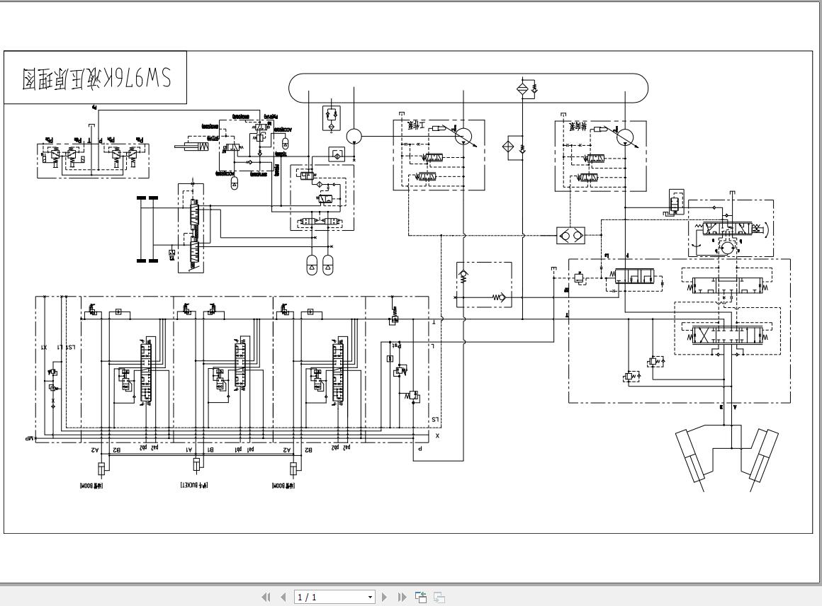
9.1 Hydraulic System
9.2 Air Conditioner
9.3 Monitor System
9.4 Control switches
9.5 Operator Station
9.6 Chassis
Related Products
-
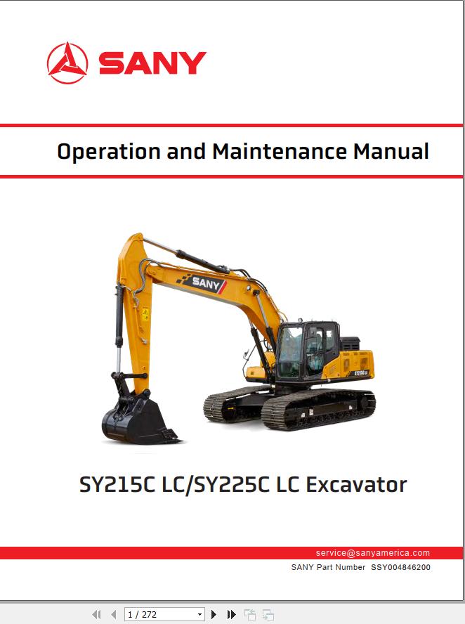
Sany Excavator SY215C LC SY225C LC Operation and Maintenance Manual SSY004846200
10 USD -
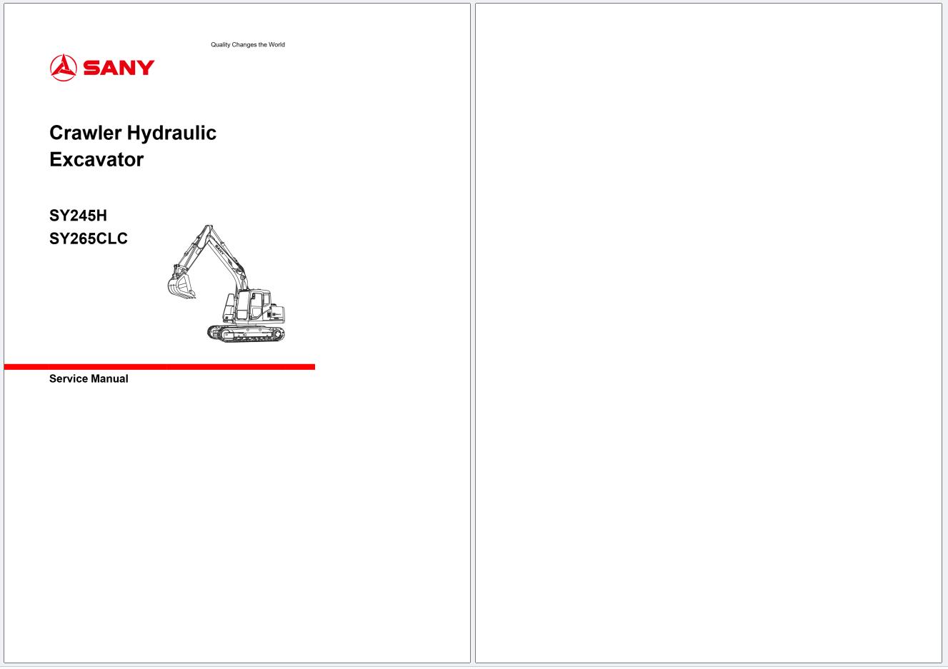
Sany Excavator SY245H SY265CLC Service Manual 2023
30 USD -
Sany Machinery Spare Parts List Shop Manual Diagram
Original price was: 200.100Current price is: 100. USD -
SANY Service Manual PDF Collection 2.95 GB
Original price was: 200.90Current price is: 90. USD -
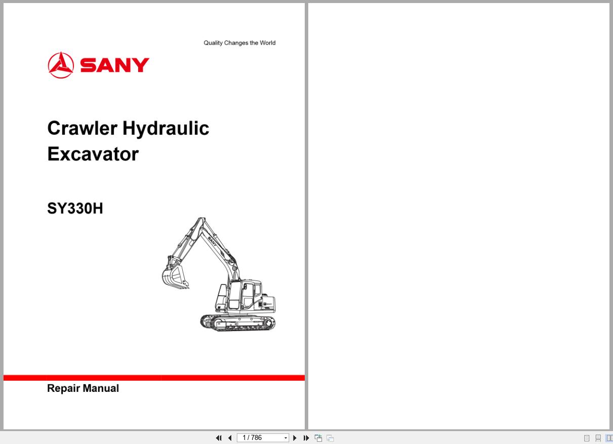
Sany Excavator SY330H Repair Manual
40 USD -
Sanyi Off-Highway Truck SRT55D Operation and Maintenance Manual
10 USD -
Sanyi Off-Highway Truck SRT45 Operation and Maintenance Manual
10 USD -
Sany Machine Full Collection Manual DVD PDF Collection
Original price was: 150.45Current price is: 45. USD