
5 ITEMSVIEW CART


Total: 98.00

Expert Support
Full Speed
100% Working
20 USD
Contents:
Section 1 – Maintenance
1.1 Read and Heed
1.2 General information
1.3 Scheduled maintenance and inspections
Section 2 – Maintenance Tables and Diagrams
2.1 Standard Hose Numbering System
2.2 Torque Specifications for Fasteners (Metric)
2.3 Torque Specifications for Fasteners (US Imperial)
2.4 Torque Specifications for Hydraulic Couplings & Hoses
2.5 MEWP Torque Specifications
2.6 Axle Torque Specifications
2.7 Axle Maintenance Intervals
2.8 Hydraulic Specifications
2.9 MEWP Specifications
2.10 Platform Capacities
2.11 Fluids
2.12 Engines
2.13 Reach Diagram
Section 3 – System Component Identification and Schematics
3.1 Electrical Symbol Chart
3.2 Hydraulic Symbol Chart
3.3 Wire Number and Colour Chart
3.4 Hydraulic Parts List
3.5 Electrical Component Parts List
3.6 Rotary Manifold Port Identification
3.7 Brake Manifold Port Identification
3.8 Drive and System Pump and Port Identification
3.9 Drive Motor Port Identification
3.10 Jib Valve Port Identification
3.11 Main Manifold Port Identification – ANSI/CSA
3.12 Main Manifold Electrical Component Identification – ANSI/CSA
3.13 Main Manifold Hydraulic Component Identification – ANSI/CSA
3.14 Major Components
3.15 Main Electrical Harness and Fuel Level Switch Harness
3.16 Engine Harness – Kubota D1305
3.17 Engine Harness Wiring Diagram – Kubota D1305
3.18 Engine Harness – Kubota WG972
3.19 Engine Harness Wiring Diagram – Kubota WG972
3.20 Lowering Throttle Valve Harness
3.21 Jib and Platform Rotate Harness
3.22 Limit Switch Connections
3.23 SGE Connections
3.24 Moba Load Cell Connections
3.25 Footswitch Connections
3.26 CANbus Cable Connections
3.27 Power Cable Connections
3.28 All Motion Alarm Connections – CE & AS
3.29 Welder Wiring – ANSI/CSA
3.30 Positive Air Shut-off Harness – Kubota D1305
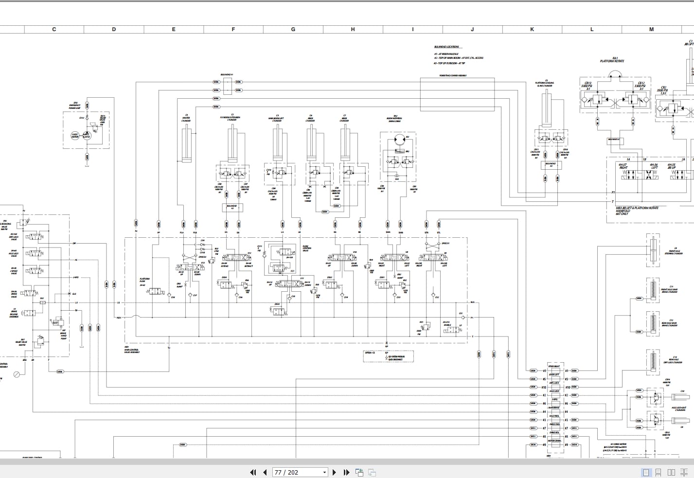
3.31 Hydraulic Schematic
3.32 Platform Control Box Wiring
3.33 Base Control Box Wiring – ANSI/CSA & AS
3.34 Base Control Box Wiring – CE
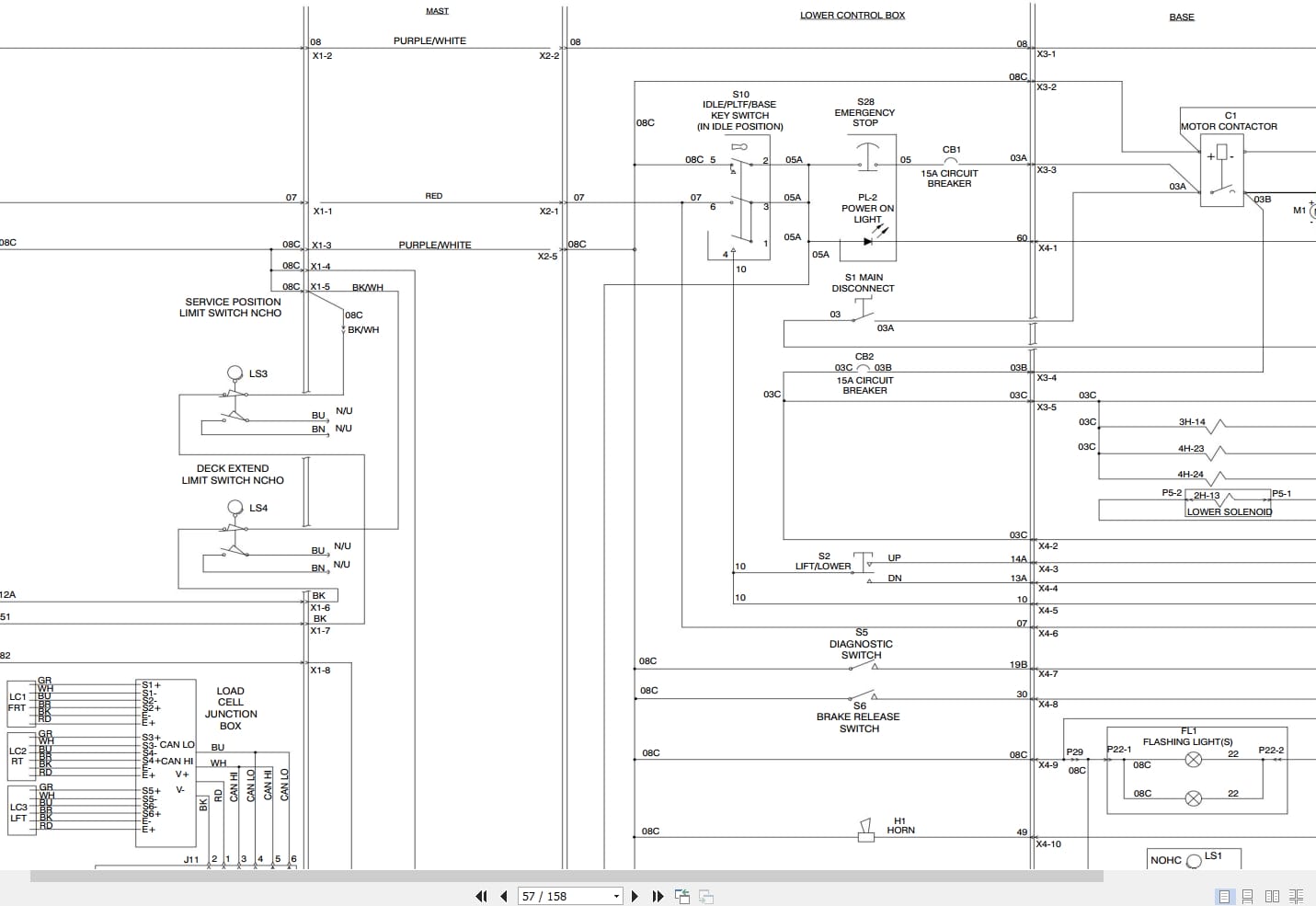
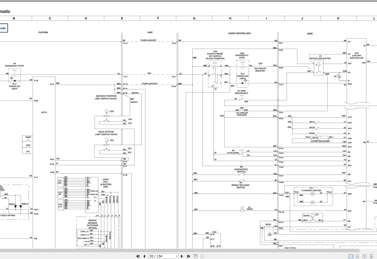
3.35 Electrical Schematic – ANSI/CSA & AS
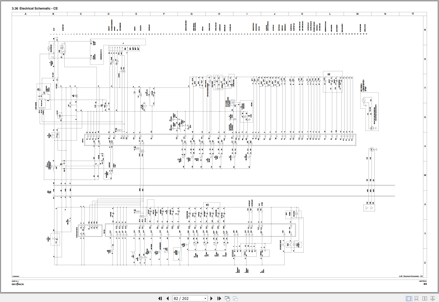
3.36 Electrical Schematic – CE
3.37 Engine Schematic – Kubota D1305
3.38 Engine Schematic – Kubota WG972
Section 4 – Troubleshooting Information
4.1 Introduction
4.2 Electrical System
4.3 Hydraulic System
Section 5 – Procedures
5.1 Safety and Workmanship
5.2 System Control Module (SCM)
5.3 Platform
5.4 Boom
5.5 Limit Switches
5.6 Turret
5.7 Engines
5.8 Generator
5.9 Hydraulic Tank
5.10 Manifold and Hydraulic Pumps
5.11 Axles
5.12 Grease Points
REALEASE :
REALEASE :
REALEASE :
REALEASE :
REALEASE :
REALEASE :

REALEASE :
30.05.2020
REALEASE :
30.05.2020
REALEASE :
REALEASE :

REALEASE :
REALEASE :
REALEASE :
REALEASE :
REALEASE :
REALEASE :
 Automotive - Heavy Equipment - Truck & Bus - Forklift - Crane