
11 ITEMSVIEW CART


Total: 640.00
Expert Support
Full Speed
100% Working
20 USD
Contents:
Section 1 – Scheduled Maintenance
1.1 Read and Heed
1.2 Maintenance and Service
1.3 Scheduled Maintenance
1.4 Owner’s Annual Inspection Record
1.5 Pre-Delivery/Maintenance Inspection Checklist
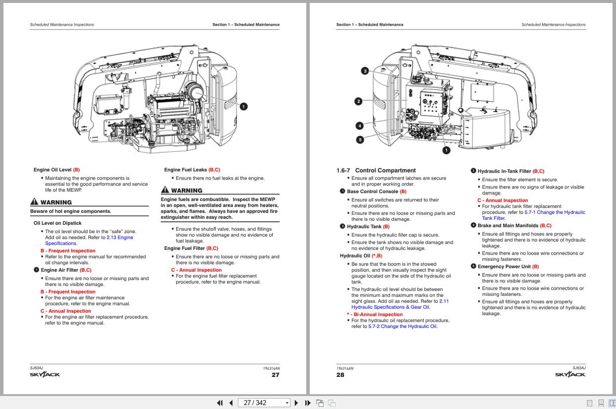
1.6 Scheduled Maintenance Inspections
1.7 Function Tests
Section 2 – Maintenance Tables and Diagrams
2.1 Standard Hose Numbering System
2.2 Torque Specifications for Fasteners (US Imperial)
2.3 Torque Specifications for Fasteners (Metric)
2.4 Torque Specifications for Hydraulic Couplings & Hoses
2.5 Axle Torque Specifications
2.6 Axles Maintenance Intervals
2.7 MEWP Torque Specifications
2.8 Maximum Platform Capacity
2.9 Tire Specifications
2.10 Floor Loading Pressure
2.11 Hydraulic Specifications & Gear Oil
2.12 Specifications & Features – Dimensions & Speeds
2.13 Engine Specifications
2.14 Dimension and Reach Diagrams – SJ63AJ
2.15 Axle Oscillation Diagrams
Section 3 – System Component Identification and Schematics
3.1 Electrical Symbol Chart
3.2 Hydraulic Symbol Chart
3.3 Wire Number and Color Code
3.4 Hydraulic Parts List
3.5 Electrical Component Parts List
3.6 Rotary Manifold Port Identification
3.7 Brake Manifold Port Identification
3.8 Drive and System Pump and Port Identifications
3.9 Drive Motor and Port Identifications
3.10 Jib Valve and Port Identifications
3.11 Main Manifold and Port Identifications
3.12 Main Manifold and Electrical Identifications
3.13 Main Manifold and Hydraulic Identifications
3.14 Main Electrical Harness and Fuel Level Switch Harness
3.15 ECU Engine Wiring Diagram – Deutz
3.16 Glow Plug Harnesses – Deutz D2011
3.17 Glow Plug Harnesses – Deutz TD2.9L
3.18 Engine Interface Harness – GM
3.19 Engine Interface Harness – Deutz TD2.9L
3.20 Lowering Throttle Valve Harness
3.21 Platform Harnesses
3.22 Platform Control Cables
3.23 Limit Switch Connections at the Base Control Box
3.24 Load Sensing Connections – CE & AS
3.25 All Motion Alarm Connections – CE & AS
3.26 SGE Schematics
3.27 SGE Platform Control Wiring Diagram
3.28 Hydraulic Generator and Oil Cooler Wiring – Base Control Box
3.29 Generator Wiring – Upper Control Box
3.30 Welder Wiring – ANSI/CSA
3.31 Load Circuit Wiring
3.32 Positive Air Shutoff Harness
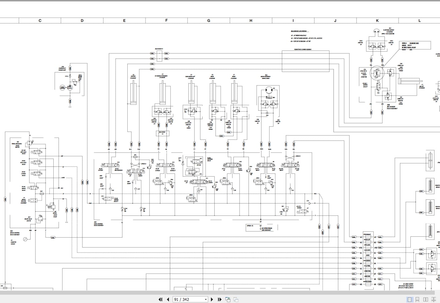
3.33 Hydraulic Schematic
3.34 Platform Control Box Wiring – ANSI/CSA – GM & Kubota
3.35 Platform Control Box Wiring – ANSI/CSA – Deutz
3.36 Platform Conrol Box Wiring – CE – Deutz TCD2.2
3.37 Platform Control Box Wiring – CE – Deutz TD2.9L & D2011
3.38 Platform Control Box Wiring – CE – Kubota WG2503
3.39 Platform Control Box Wiring – AS – Deutz
3.40 Base Control Box Wiring – ANSI/CSA – GM
3.41 Base Control Box Wiring – ANSI/CSA – Deutz TD2.9L
3.42 Base Control Box Wiring – ANSI/CSA – Deutz TD2.9L with Positive Air Shutoff Option
3.43 Base Control Box Wiring – ANSI/CSA – Deutz D2011
3.44 Base Control Box Wiring – ANSI/CSA – Deutz D2011 with Positive Air Shut-Off
3.45 Base Control Box Wiring – Perkins 2.2TA
3.46 Base Control Box Wiring – CE – Deutz TCD2.2
3.47 Base Control Box Wiring – CE – Deutz TD2.9L
3.48 Base Control Box Wiring – CE – Deutz D2011
3.49 Base Control Box Wiring – CE – Kubota WG2503
3.50 Base Control Box Wiring – AS – Deutz D2011
3.51 Electrical Schematic – ANSI/CSA – GM
3.52 Electrical Schematic – ANSI/CSA – Kubota WG2503 (S/N 95301738 and below)
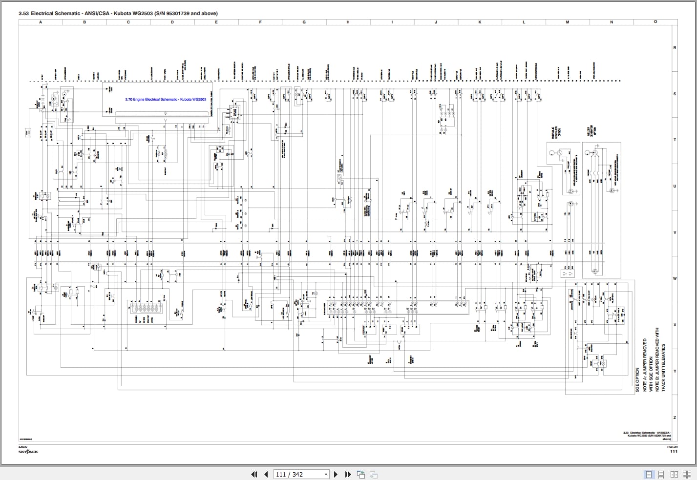
3.53 Electrical Schematic – ANSI/CSA – Kubota WG2503 (S/N 95301739 and above)
3.54 Electrical Schematic – ANSI/CSA – Deutz TD2.9L (S/N 95301738 and below)
3.55 Electrical Schematic – ANSI/CSA – Deutz TD2.9L (S/N 95301739 and above)
3.56 Electrical Schematic – ANSI/CSA – Deutz D2011 (S/N 95301738 and below)
3.57 Electrical Schematic – ANSI/CSA – Deutz D2011 (S/N 95301739 and above)
3.58 Electrical Schematic – ANSI/CSA – Perkins 2.2TA (S/N 95301738 and below)
3.59 Electrical Schematic – ANSI/CSA – Perkins 2.2TA (S/N 95301739 and above)
3.60 Electrical Schematic – CE – Deutz TCD2.2
3.61 Electrical Schematic – CE – Deutz TD2.9L Diesel (S/N 95301738 and below)
3.62 Electrical Schematic – CE – Deutz TD2.9L Diesel (S/N 95301739 and above)
3.63 Electrical Schematic – CE – Deutz D2011 (S/N 95301738 and below)
3.64 Electrical Schematic – CE – Deutz D2011 (S/N 95301739 and above)
3.65 Electrical Schematic – CE – Kubota WG2503 (S/N 9530178 and below)
3.66 Electrical Schematic – CE – Kubota WG2503 (S/N 9530179 and above)
3.67 Electrical Schematic – AS – Deutz D2011 (S/N 95301738 and below)
3.68 Electrical Schematic – AS – Deutz D2011 (S/N 95301739 and above)
3.69 Engine Electrical Schematic – GM
3.70 Engine Electrical Schematic – Kubota WG2503
3.71 Engine Electrical Schematic – CE – Kubota WG2503
3.72 Engine Electrical Schematic – Deutz TD2.9L
3.73 Engine Electrical Schematic – CE – Deutz TD2.9L Diesel
3.74 Engine Interface Wiring – Deutz TD2.9L
3.75 Engine Interface Harness – Perkins 2.2TA
3.76 Engine OEM Harness – Perkins 2.2TA
3.77 Engine Component Harness – Perkins 2.2TA
3.78 Engine Electrical Schematic – Deutz TCD2.2
3.79 Engine Interface Harness – Deutz TCD2.2
Section 4 – Troubleshooting Information
4.1 Introduction
4.2 Electrical System (ANSI/CSA)
4.3 Electrical System (CE & AS)
4.4 Hydraulic System (ANSI/CSA)
4.5 Hydraulic System (CE & AS)
4.6 Load Sensing System (CE)
Section 5 – Procedures
5.1 General
5.2 Platform
5.3 Boom
5.4 Turret
5.5 Deutz Diesel Engine
5.6 Kubota WG2503 Dual Fuel Engine
5.7 Hydraulic Tank
5.8 Manifold and Hydraulic Pumps
5.9 Axles
5.10 Grease Points
5.11 Load Sensing System
5.12 Generator
REALEASE :
REALEASE :
REALEASE :
REALEASE :
REALEASE :
REALEASE :
REALEASE :
REALEASE :

REALEASE :
REALEASE :
REALEASE :
REALEASE :
REALEASE :
REALEASE :

REALEASE :
30.05.2020
REALEASE :
30.05.2020
 Automotive - Heavy Equipment - Truck & Bus - Forklift - Crane