
14 ITEMSVIEW CART


Total: 1,577.00

Expert Support
Full Speed
100% Working
15 USD
Contents:
1.0 Platform Related Parts
Figure 1.1. Entrance Gates and Chains
Figure 1.2. Gate Latch Assembly
Figure 1.3. Side Railings
Figure 1.4. Extension Platform Railings
Figure 1.5. Extension Slide Railing
Figure 1.6. Quick Release Pins
Figure 1.7. Main Platform Assembly
Figure 1.8. Extension Platform Assembly
Figure 1.9a. Platform Control Console Assembly (Toggle Switch)
Figure 1.9b. Platform Control Console Assembly (Rotary Switch)
Figure 1.10. Enable Controller Assembly
Figure 1.11. Platform AC Outlet Assembly
Figure 1.12. Control Cable Assemblies
2.0 Scissor Related Parts
Figure 2.1. Scissor Arm Weldments
Figure 2.2. Scissor Arm Assembly, Accessories and Hardware
Figure 2.3. Beeper, Light & Load Sensing Assembly (CE)
Figure 2.4. Scissor Stack Assembly Mounting
Figure 2.5. Scissor Arm Assembly Connecting Hardware
Figure 2.6. Scissor Arm Limit Switch Assemblies
Figure 2.7. Lift Cylinder Assembly and Mounting Hardware
Figure 2.8. Holding Valve Assembly (ANSI/CSA)
Figure 2.9. Holding Valve Assembly (CE)
3.0 Base Related Parts
Figure 3.1. Base, Axle & Wheels
Figure 3.1. Base, Axle & Wheels (Continued)
Figure 3.2. Pothole Protection Device
Figure 3.3. Control Module Assembly
Figure 3.4. Tire Assembly
Figure 3.5. Steer Mechanism
Figure 3.6. Steer Assembly
Figure 3.7. Rear Axle Assembly
Figure 3.8. Brake Cylinder Assembly
Figure 3.9. Steer Cylinder Assembly
Figure 3.10. Hydraulic Hose Connections
Figure 3.11. Steering Manifold Assembly
Figure 3.12. Base Control Console Hardware
Figure 3.13. Base Control Harness and Switches
4.0 Hydraulic Tray Related Parts
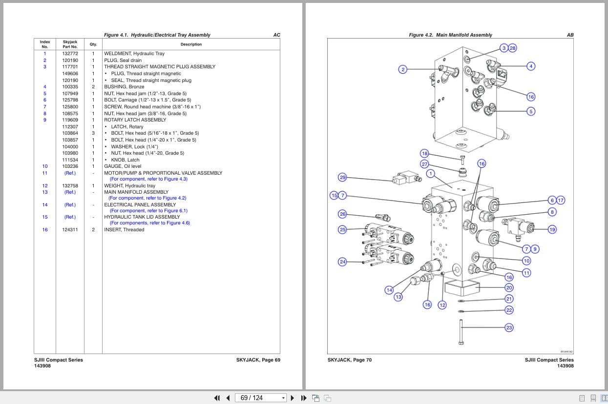
Figure 4.1. Hydraulic/Electrical Tray Assembly
Figure 4.2. Main Manifold Assembly
Figure 4.3. Motor and Pump Assembly
Figure 4.4. Emergency Lowering Manifold Assembly
Figure 4.5. Proportional Manifold Assembly
Figure 4.6. Hydraulic Tank Lid Assembly
Figure 4.7. Hydraulic Hose Connections
5.0 Battery Tray Related Parts
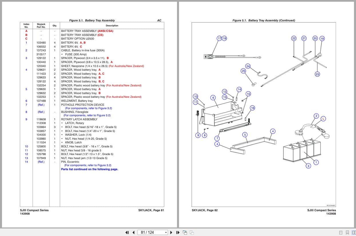
Figure 5.1. Battery Tray Assembly
Figure 5.2. Battery Charger
6.0 Electrical Related Parts
Figure 6.1. Electrical Panel and Hardware Assembly
Figure 6.2. Main Manifold Harness
Figure 6.3. Rear Manifold Harness
Figure 6.4. Horn/Flashing Light, Tilt Switch & Holding Valve Harnesses (ANSI/CSA)
Figure 6.5. Horn, Control Module & Holding Valve Harnesses (CE)
Figure 6.6. Elevate Telematics Harness
Figure 6.6. Elevate Telematics Harness
7.0 Optional Equipment
Figure 7.1. 24VDC Inverter and Hardware
Figure 7.2. Inverter Assembly
Figure 7.3. Inverter Label Placement
Figure 7.4. Platform Air Supply Hose
Figure 7.5. Slate Grey Label Option
Figure 7.6. Flashing Amber Light Option
Figure 7.7. Dual Flashing Amber Light Option (Diagonal) (ANSI/CSA)
Figure 7.8. Tool Caddy
Figure 7.9. Elevate Telematics
Figure 7.10 Secondary Guarding Lift Enable Kit
Figure 8.1. Label Kit
8.0 Label Kit
Figure 8.2. Label – Platform Control Console
Figure 8.3. Labels – Miscellaneous.
Figure 8.4. Labels – Sides
9.0 Fluid Table
Table 9.1. SJ3 Scissor Fluids
REALEASE :
REALEASE :

REALEASE :
REALEASE :
REALEASE :
REALEASE :

REALEASE :
30.05.2020
REALEASE :
30.05.2020
REALEASE :
REALEASE :
REALEASE :
REALEASE :
REALEASE :
REALEASE :
REALEASE :
REALEASE :
 Automotive - Heavy Equipment - Truck & Bus - Forklift - Crane