
0 ITEMSVIEW CART


✓
Expert Support
✓
Full Speed
✓
100% Working
Skyjack DC Electric Scissors SJIII3220 to SJIII4632 Parts Manual 165974AM 2022
Size: 10.59 MB
Format: PDF
Language: English
Brand: Skyjack
Type of Machine: DC Electric Scissors
Type of Manual: Parts Manual
Model: Skyjack SJIII3220, SJIII3226, SJIII4620, SJIII4626, SJIII4632
Serial Number:
SJIII3220 60004189 to 60999999
SJIII3226 27017551 to 27999999
SJIII46XX 70017596 to 70199999
Part Number: 165974AM
Publication Date: 2022
Number of Pages: 217 Pages
15 USD
- Description
Description
Contents:
Foreword
General
Parts Ordering Information
Method of Listing
Quantities
How To Order Repair Parts
Section 1 – Platform Related Parts
1.1 Entrance Gates and Chains
1.2 Gate Latch Assembly
1.3 Side Railings – Rigid
1.4 Side Railings – Hinged
1.5 Extension Platform Railing Assembly
1.6 Extension Handrail
1.7 Quick Release Pins
1.8 Main Platform Assembly
1.9 Extension Platform Assembly
1.10 Extension Cylinder Mounting Hardware
1.11 Extension Cylinder Assembly
1.12 Hose Connections – Powered Extension (Models 3220/4620)
1.13 Hose Connections – Powered Extension (Model 4626)
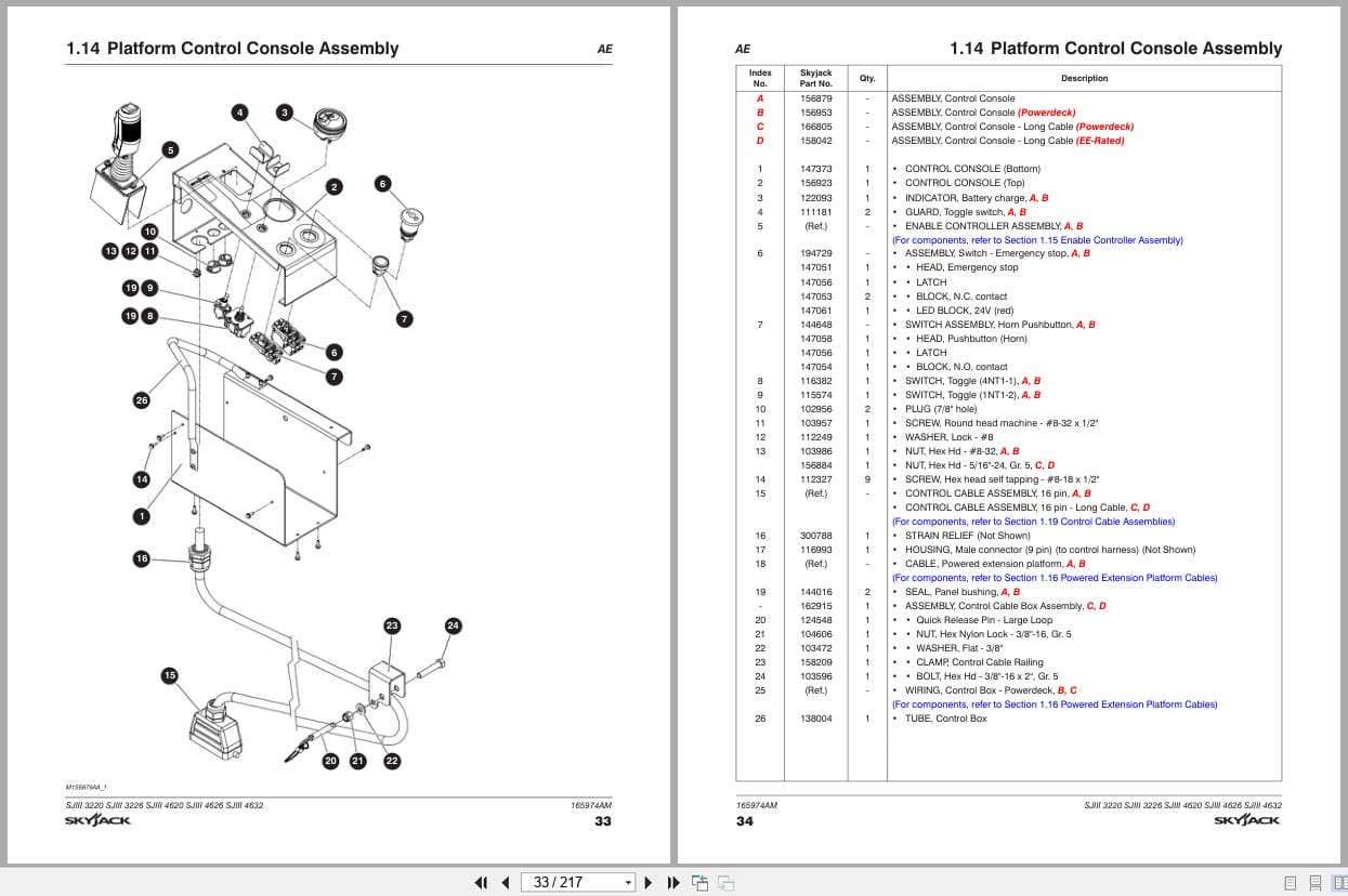
1.14 Platform Control Console Assembly
1.15 Enable Controller Assembly
1.16 Powered Extension Platform Cables
1.17 Extension Platform Harness
1.18 Extension Platform Control Console
1.19 Control Cable Assemblies
1.20 Platform AC Outlet
Section 2 – Scissor Related Parts
2.1 Scissor Stack Assembly (Model 3220/4620)
2.2 Scissor Stack Assembly (Model 3226/4626)
2.3 Scissor Stack Assembly (Model 4632)
2.4 Scissor Stack Assembly – Mounting Hardware
2.5 Scissor Stack Assembly – Connecting Hardware
2.6 Limit Switch Assembly (Scissor Stack)
2.7 Lift Cylinder and Mounting Hardware
2.8 Holding Valve Assembly (Model 3220/4620)
2.9 Holding Valve Assembly (Model 3226/4626/4632)
Section 3 – Base Related Parts
3.1 Base Assembly
3.2 Pothole Protection Device
3.3 Brake Assembly
3.4 Wheel Assembly
3.5 Tie Rod Assembly
3.6 Steer Cylinder Assembly
3.7 Pin Brake Cylinder Assembly
3.8 Rear Drive Manifold Assembly
3.9 Brake Release Manifold Assembly (Models 46xx)
3.10 Front Hub and Spindle Assembly
3.11 Hydraulic Hose Connections – Pin Brake
3.12 Hydraulic Hose – Disc Brake (Models 46xx)
3.13 Base Control Console
3.14 Base Control Console – B
Section 4 – Hydraulic Tray Related Parts
4.1 Hydraulic/Electrical Tray Assembly
4.2 Main Manifold Assembly
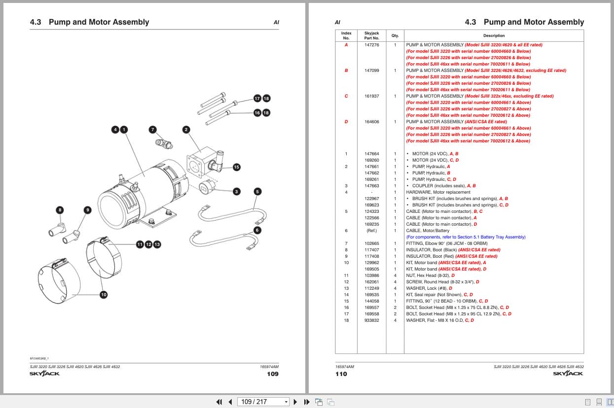
4.3 Pump and Motor Assembly
4.4 Proportional Manifold Assembly
4.5 Hydraulic Hose Connections (Hydraulic/Electrical Tray)
Section 5 – Battery Tray Related Parts
5.1 Battery Tray Assembly
5.2 Battery Charger – Delta-Q
5.3 Battery Charger – Signet
Section 6 – Electrical Related Parts
6.1 Electrical Panel Hardware Assembly
6.2 Electrical Panel Hardware Assembly (EE-Rated)
6.3 Main Manifold Harness
6.4 Rear Manifold Harness
6.5 Horn/Flashing Light and Tilt Switch Harnesses
6.6 Holding Valve, Charger Cutout, and Pressure Switch
6.7 Electrical Panel Powerdeck Modification
6.8 Elevate Telematics Harness
Section 7 – Optional Equipment
7.1 24VDC Inverter Assembly (ANSI/CSA)
7.2 Inverter Assembly
7.3 Air Hose to Platform Assembly
7.4 Work Light Option (ANSI/CSA)
7.5 Flashing Amber Light Option
7.6 Dual Flashing Amber Light Option (Excluding EE-Rated)
7.7 Light Duty Pipe Rack Option
7.8 Black Logo Labels Option (Model 4626)
7.9 Board Carrier (Models 3226/4632 including EE-rated)
7.10 Tool Caddy
7.11 Heavy Duty Pipe Rack Assembly
7.12 Elevate Telematics
7.13 Secondary Guarding Lift Enable Kit
Section 8 – Labels
8.1 Label Kit
8.2 Labels – Platform Control Console
8.3 Labels – Miscellaneous
8.4 Labels – Left & Right Sides (Chassis)
8.5 Labels – Chassis (Front & Top)
8.6 Labels – Rear (Scissor and Platform)
8.7 Labels – Rear (Chassis)
Section 9 – Fluids
9.1 Fluid Table
Section 10 – Appendix A – Motor Controller
10.1 Platform Control Console Assembly
10.2 Platform Control Box (Top)
10.3 Enable Controller Assembly
10.4 Hydraulic/Electrical Tray Assembly – Welded Tank
10.5 Hydraulic/Electrical Tray – Welded Tank
10.6 Hydraulic/Electrical Tray Assembly – Plastic Tank
10.7 Hydraulic Tank Lid Assembly – Welded Tank
10.8 Hydraulic Tank Lid Assembly – Plastic Tank
10.9 Motor/Pump Assembly – Plastic Tank
10.10 Main Manifold Assembly – Welded Tank
10.11 Main Manifold Assembly – Plastic Tank
10.12 Hydraulic Hose Connections – Welded Tank
10.13 Hydraulic Hose Connections – Plastic Tank
10.14 Electrical Panel, Hardware and Wire Kit
10.15 RST Wire Assemblies
10.16 Main Manifold Harness
10.17 Rear Manifold Harness
10.18 Charger, Horn/Flashing Lights, Tilt Switch Harnesses
10.19 Control Cable Assemblies
10.20 Powerdeck Conversion Kit – Motor Controller
Related Products
-
Skyjack Vertical Mast Lifts SJ20 Parts Manual 238885ACA 2023
15 USDSize: 6.43 MBFormat: PDFLanguage: EnglishBrand: SkyjackType of Machine: Vertical Mast LiftsType of Manual: Parts ManualModel: Skyjack SJ20 Vertical Mast LiftsSerial Number: A601000001 to A601000905Part Number: 238885ACAPublication Date: 2023Number of Pages: 116 Pages
REALEASE :
REALEASE :
-
Skyjack Vertical Mast Lifts SJ20 Operating Manual 236504AFA 2022
10 USDSize: 5.17 MBFormat: PDFLanguage: EnglishBrand: SkyjackType of Machine: Vertical Mast LiftsType of Manual: Operating ManualModel: Skyjack SJ20 Vertical Mast LiftsSerial Number: A601000001 – A601000905Part Number: 236504AFAPublication Date: 2022Number of Pages: 94 Pages
REALEASE :
REALEASE :
-
Skyjack Vertical Mast Lifts SJ12E SJ16E SJ20E Service Manual 241914ADA 2023
20 USDSize: 10.70 MBFormat: PDFLanguage: EnglishBrand: SkyjackType of Machine: Vertical Mast LiftsType of Manual: Service Manual, Electrical SchematicModel: Skyjack SJ12E, SJ16E, SJ20E Vertical Mast LiftsSerial Number: A601000906 – A601999999Part Number: 241914ADAPublication Date: 2023Number of Pages: 154 Pages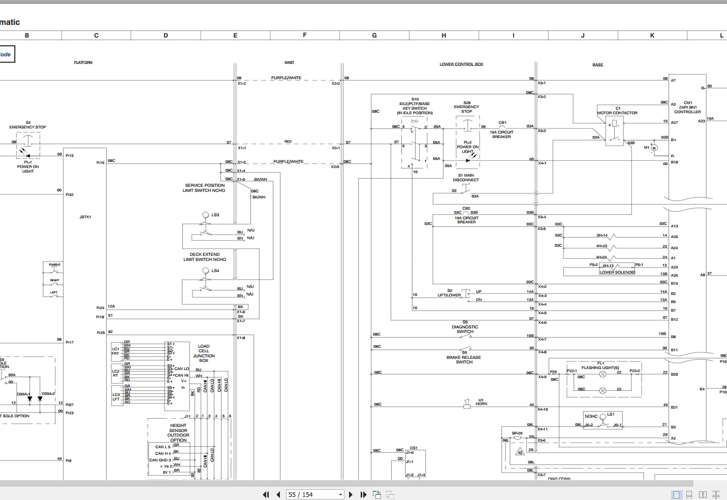
REALEASE :
REALEASE :
-
Skyjack Vertical Mast Lifts SJ12E SJ16E SJ20E Parts Manual 241913ADA 2023
15 USDSize: 7.44 MBFormat: PDFLanguage: EnglishBrand: SkyjackType of Machine: Vertical Mast LiftsType of Manual: Parts ManualModel: Skyjack SJ12E, SJ16E, SJ20E Vertical Mast LiftsSerial Number: A601000906 – A601999999Part Number: 241913ADAPublication Date: 2023Number of Pages: 138 Pages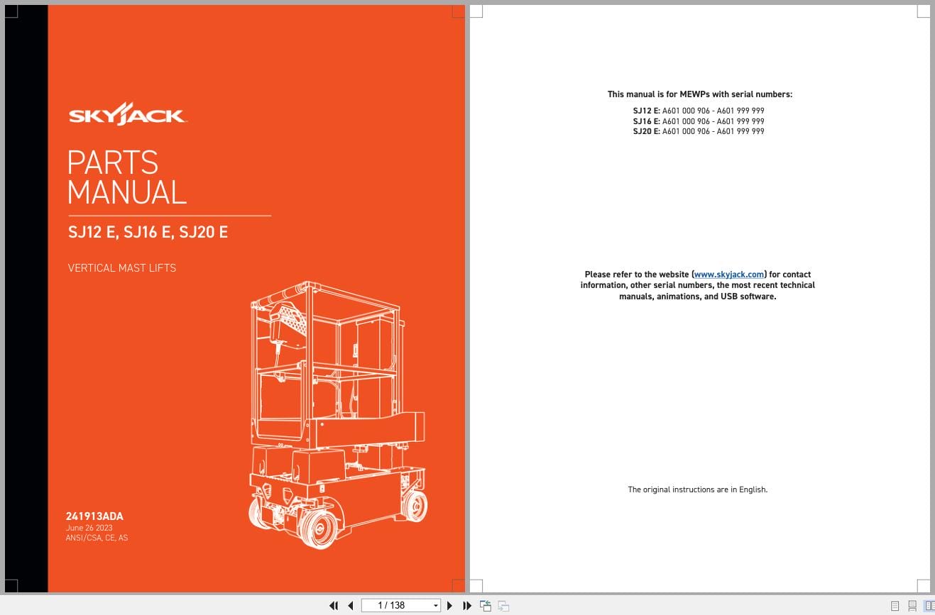
REALEASE :
REALEASE :
-
Skyjack NA 4.93GB PDF Operating Parts Service Manuals
Original price was: 200.140Current price is: 140. USDThis is a service information package, you will need to use this to repair a vehicleHot-30%
REALEASE :
REALEASE :
-
Skyjack Vertical Mast Lifts SJ12E SJ16E SJ20E Operating Manual 243762ABA 2022
10 USDSize: 5.67 MBFormat: PDFLanguage: EnglishBrand: SkyjackType of Machine: Vertical Mast LiftsType of Manual: Operating ManualModel: Skyjack SJ12E, SJ16E, SJ20E Vertical Mast LiftsSerial Number: A601001639 & abovePart Number: 243762ABAPublication Date: 2022Number of Pages: 92 Pages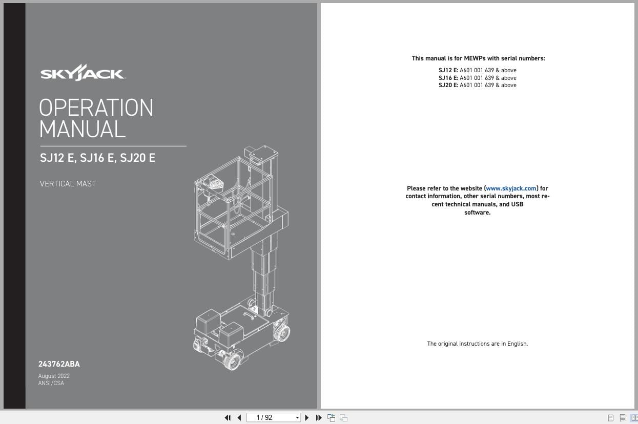
REALEASE :
REALEASE :
-
Skyjack Lift Aerial Working Platform AWP All Models 2020 Documentation PDF DVD
Original price was: 200.110Current price is: 110. USDSkyjack Lift Aerial Working Platform AWP All Models 2020 Documentation PDF DVDSize: 6.39 GBFormat: PDFLanguage: EnglishBrand: Skyjack LiftAmount of DVD: 1 DVDWindow: All Window 32 & 64 bit, Mac OSType of Vehicle: Aerial working platform (AWP)Type of Document: Operating – Parts – Service Manuals PDFHot-45%
REALEASE :
30.05.2020
REALEASE :
30.05.2020
-
Skyjack Vertical Mast Lifts SJ20 Service Manual 238886ADA 2023
20 USDSize: 9.74 MBFormat: PDFLanguage: EnglishBrand: SkyjackType of Machine: Vertical Mast LiftsType of Manual: Service Manual, Electrical SchematicModel: Skyjack SJ20 Vertical Mast LiftsSerial Number: A601000001 to A601000905Part Number: 238886ADAPublication Date: 2023Number of Pages: 158 Pages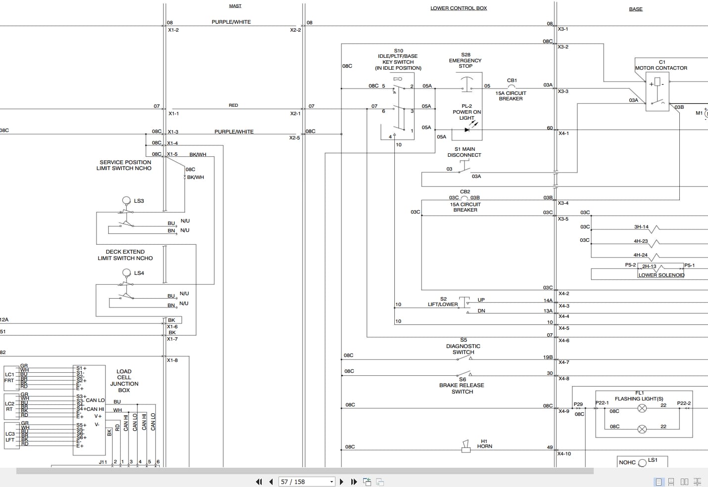
REALEASE :
REALEASE :