
13 ITEMSVIEW CART


Total: 975.00

Expert Support
Full Speed
100% Working
15 USD
Contents:
Foreword
General
Parts Ordering Information
Method of Listing
Quantities
How To Order Repair Parts
Section 1 – Platform
1.1 Platform Group
1.2 Main Platform and Extension
1.3 Main Platform
1.4 Extension Platform Assembly
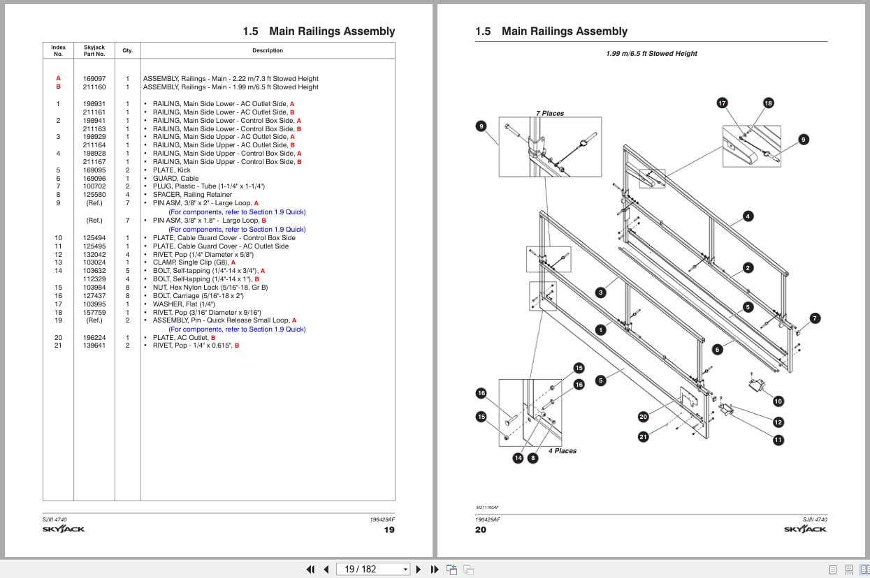
1.5 Main Railings Assembly
1.6 Extension Railing Assembly
1.7 Full Gate Entrance Assembly
1.8 Half Gate Entrance Assembly (ANSI/CSA, CE & KC)
1.9 Quick Release Pin Assembly
1.10 Gate Latch Assembly
1.11 Extension Handrail Assembly
1.12 Platform Control Box Assembly
1.13 Control Console Assembly
1.14 Enable Controller Assembly
1.15 Platform A/C Outlet Assembly
1.16 Anti-Overrising System Assembly (KC Only)
Section 2 – Scissor
2.1 Scissors
2.2 Scissor Mounting Hardware Assembly
2.3 Scissor Connecting Hardware Assembly
2.4 Lift Cylinders
2.5 Holding Valve Manifold Assembly
2.6 Hydraulic Hose Connections – Scissors
2.7 Limit Switch
2.8 Horn Assembly
2.9 Load Sensing and Transducer Module Assembly (CE & AS)
2.10 Pressure Switch (KC Only)
Section 3 – Base
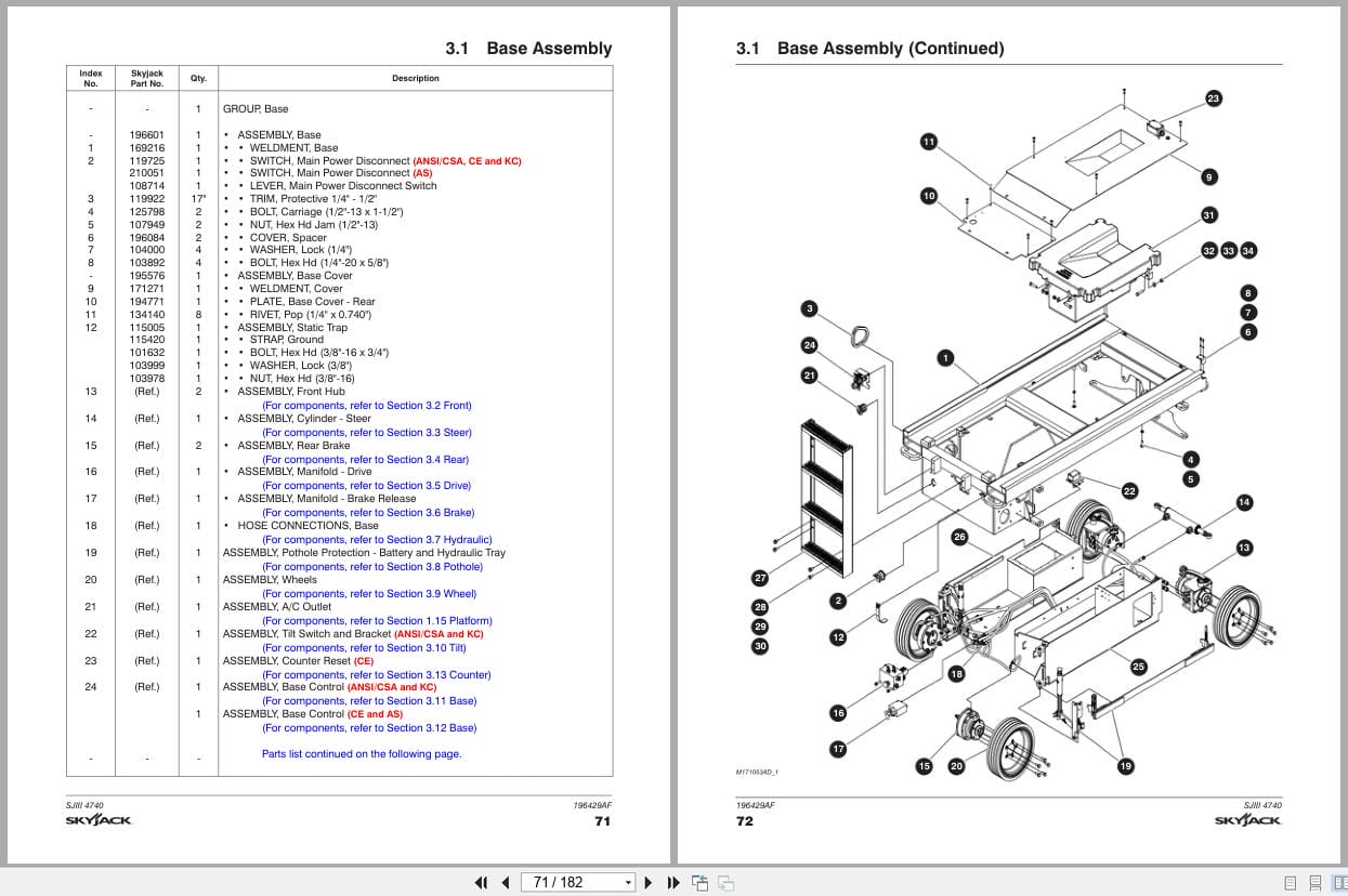
3.1 Base Assembly
3.2 Front Hub Assembly
3.3 Steer Cylinder Assembly
3.4 Rear Brake Assembly
3.5 Drive Manifold Assembly
3.6 Brake Release Manifold Assembly
3.7 Hydraulic Hose Connections Base
3.8 Pothole Protection Assembly
3.9 Wheel Assembly
3.10 Tilt Switch and Bracket Assembly
3.11 Base Control Assembly (ANSI/CSA & KC)
3.12 Base Control Assembly (CE & AS)
3.13 Counter Reset (CE)
Section 4 – Hydraulic Tray
4.1 Hydraulic Tray
4.2 Hydraulic Tank Lid
4.3 Emergency Lowering
4.4 Motor and Pump
4.5 Main Manifold
4.6 Hydraulic Hose Connections – Hydraulic Tray
Section 5 – Battery Tray
5.1 Battery Tray Assembly
5.2 Battery Assembly
5.3 Battery Charger – Delta-Q
5.4 Battery Charger – Signet
Section 6 – Electrical Related Parts
6.1 Electrical Panel Assembly
6.2 Control Cable Assembly
6.3 Rear Manifold Harness
6.4 Main Manifold Harness
6.5 Electrical Harnesses
6.6 Battery Cables
6.7 Dual Flashing Light Harness (ANSI/CSA only)
6.8 Anti-Overrising System Harnesses (KC Only)
6.9 Elevate Telematics Harness
Section 7 – Optional Equipment
7.1 Board Carrier Assembly (ANSI/CSA, CE & AS)
7.2 Inverter Subgroup (ANSI/CSA)
7.3 Inverter Wiring (ANSI/CSA)
7.4 Inverter (ANSI/CSA)
7.5 Dual Flashing Light Assembly (ANSI/CSA & CE)
7.6 Telematics Option – Morey (ANSI/CSA)
7.7 Telematics Option – ZTR (ANSI/CSA)
7.8 Telematics Harness – Morey (ANSI/CSA)
7.9 Heavy Duty Pipe Rack Assembly (ANSI/CSA, CE & AS)
7.10 Tool Caddy
7.11 Residual Current Device Assembly (CE)
7.12 Aluminum Control Box Guard Assembly (CE)
7.13 Elevate Telematics
7.14 Railing Kit – Full Gate
7.15 Railing Kit – Half Gate
7.16 Secondary Guard Lift Enable (CE Only)
Section 8 – Labels
8.1 Label Kit
8.2 Labels – Platform Control Console
8.3 Labels – Miscellaneous
8.4 Labels – Left & Right Side
8.5 Labels – Front, Rear and Top
8.6 Labels – Hoses Numbers (KC only)
8.7 Labels – Hose Layout (KC only)
8.8 Labels – Quickstart (KC only)
Section 9 – Tables
9.1 Fluid Table
REALEASE :
REALEASE :

REALEASE :
30.05.2020
REALEASE :
30.05.2020
REALEASE :
REALEASE :
REALEASE :
REALEASE :
REALEASE :
REALEASE :
REALEASE :
REALEASE :

REALEASE :
REALEASE :
REALEASE :
REALEASE :
 Automotive - Heavy Equipment - Truck & Bus - Forklift - Crane