
4 ITEMSVIEW CART


Total: 180.00
Expert Support
Full Speed
100% Working
20 USD
Contents:
Section 1 – Scheduled Maintenance
1.1 Read and Heed
1.2 Maintenance and Inspection Schedule
1.3 Hydraulic System & Component Maintenance and Repair
1.4 About this Section
1.5 Owner’s Annual Inspection Record
1.6 Pre-Delivery/Maintenance Inspection Checklist
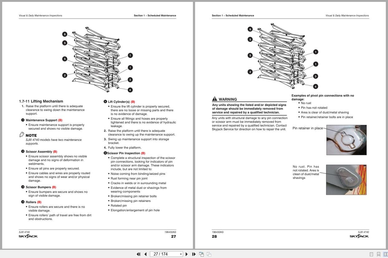
1.7 Visual & Daily Maintenance Inspections
1.8 Function Tests
Section 2 – Maintenance Tables and Diagrams
2.1 Specifications & Features
2.2 Torque Specifications for Fasteners (US)
2.3 Torque Specifications for Fasteners (Metric)
2.4 Torque Specifications for Hydraulic Couplings & Hoses
2.5 Torque Specifications
2.6 Maximum Platform Capacities (Evenly Distributed)
2.7 Floor Loading Pressure
Section 3 – System Component Identification and Schematics
3.1 Electrical Symbol Chart
3.2 Hydraulic Symbol Chart
3.3 Wire Number and Color Code
3.4 AC Cord Color Code
3.5 Hydraulic Parts List
3.6 Electrical Parts List
3.7 Drive, Brake Release and E-Lowering Manifold and Port Identification
3.8 Holding Valve and Port Identification
3.9 Platform Control Console
3.10 Base Control Console
3.11 Control Cable
3.12 High Speed Limit Switch Wiring
3.13 Anti-Overrising Limit Switch Wiring Diagrams
3.14 Hourmeter (CE)
3.15 Harness Wiring
3.16 Telematics Harness – ZTR
3.17 Battery Cable Connections
3.18 Main Manifold and Port Identidication
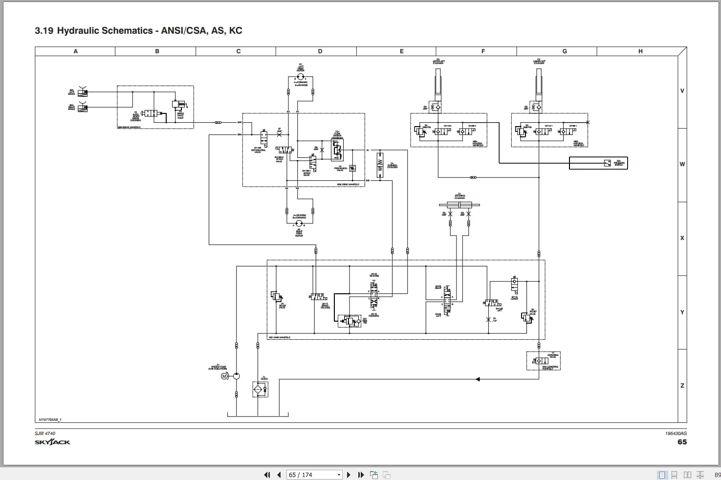
3.19 Hydraulic Schematics – ANSI/CSA, AS, KC
3.20 Hydraulic Schematics – CE & AS
3.21 Main Manifold Harness (ANSI/CSA)
3.22 Main Manifold Harness (CE, AS & KC)
3.23 Elevate Telematics Harness
3.24 Electrical Panel (ANSI/CSA), S/N 70 201 095 & below
3.25 Electrical Panel (ANSI/CSA), S/N 70 201 096 & above
3.26 Electrical Panel (CE), S/N 70 201 095 & below
3.27 Electrical Panel (CE), S/N 70 201 096 & above
3.28 Electrical Panel (AS), S/N 70 201 095 & below
3.29 Electrical Panel (AS), S/N 70 201 096 & above
3.30 Electrical Panel (KC), S/N 70 201 095 & below
3.31 Electrical Panel (KC), S/N 70 201 096 & above
3.32 Electrical Panel – Inverter Option
3.33 Telematics Wiring – Morey (ANSI/CSA)
3.34 Load Sensing and Beeper (CE & AS)
3.35 Horn/Tilt Switch/Flashing Light
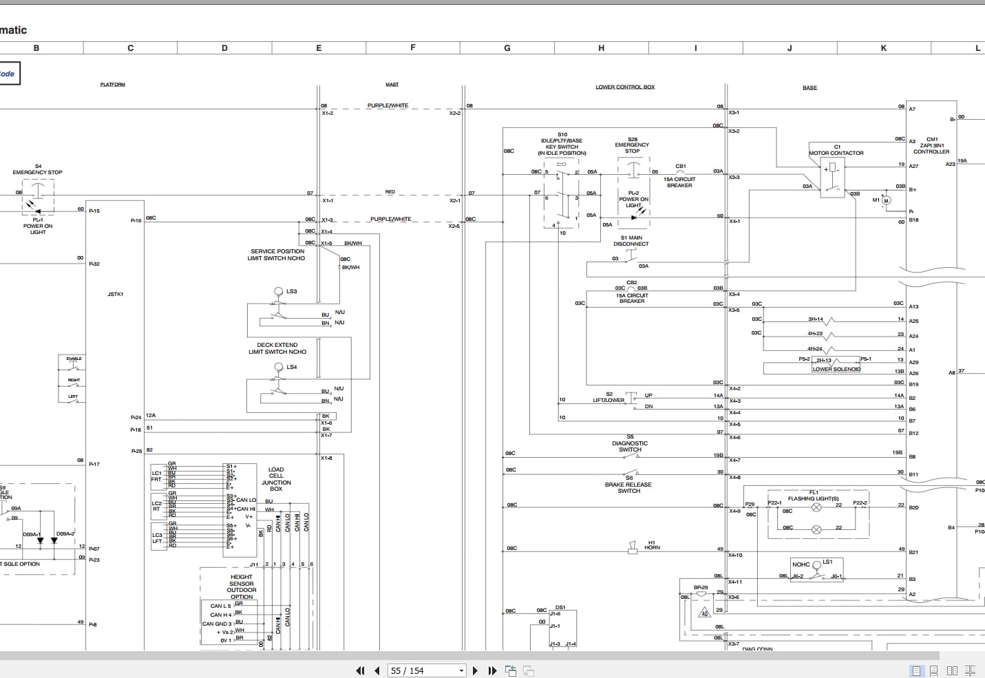
3.36 Electrical Schematic – ANSI/CSA (All Options), S/N 70 201 095 & below
3.37 Electrical Schematics – ANSI/CSA (All Options), S/N 70 201 096 & above
3.38 Electrical Schematic – ANSI/CSA (No Options), S/N 70 201 095 & below
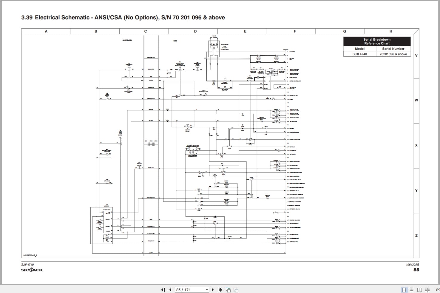
3.39 Electrical Schematic – ANSI/CSA (No Options), S/N 70 201 096 & above
3.40 Electrical Schematic (CE – All Options), S/N 70 201 095 & below
3.41 Electrical Schematic (CE – All Options), S/N 70 201 096 & above
3.42 Electrical Schematic (AS – All Options), S/N 70 201 095 & below
3.43 Electrical Schematic (AS – All Options), S/N 70 201 096 & above
3.44 Electrical Schematic (KC – All Options), S/N 70 201 095 & below
3.45 Electrical Schematic (KC – All Options), S/N 70 201 096 & above
Section 4 – Troubleshooting Information
4.1 Introduction
4.2 Electrical System – ANSI/CSA & KC
4.3 Electrical System – CE & AS
4.4 Hydraulic System – ANSI/CSA & KC
4.5 Hydraulic System – CE & AS
Section 5 – Procedures
5.1 General
5.2 Platform
5.3 Base
5.4 Scissors
5.5 Load Sensing System with a GP-102 Controller
5.6 Load Sensing System with a GP-108 Controller
REALEASE :
REALEASE :
REALEASE :
REALEASE :
REALEASE :
REALEASE :
REALEASE :
REALEASE :
REALEASE :
REALEASE :
REALEASE :
REALEASE :

REALEASE :
REALEASE :

REALEASE :
30.05.2020
REALEASE :
30.05.2020
 Automotive - Heavy Equipment - Truck & Bus - Forklift - Crane