
0 ITEMSVIEW CART

✓
Expert Support
✓
Full Speed
✓
100% Working
Skyjack Rough Terrain Scissors SJ6826RT SJ6832RT Parts Manual 143898AF 2023
Size: 10.43 MB
Format: PDF
Language: English
Brand: Skyjack
Type of Machine: Rough Terrain Scissors
Type of Manual: Parts Manual
Model: Skyjack SJ6826RT, SJ6832RT Rough Terrain Scissors
Serial Number: 37002164 – 37002787
Part Number: 143898AF
Publication Date: 2023
Number of Pages: 152 Pages
15 USD
- Description
Description
Contents:
Platform And Related Parts
Figure 1.1. Gate Assembly
Figure 1.2. Platform Railings
Figure 1.3. Extension Platform Railings
Figure 1.4. Main and Extension Platform Assembly
Figure 1.5. Gate Latch Assembly
Figure 1.6. Quick Release Pins
Figure 1.7. Air Hose to Platform Assembly
Figure 1.8. Outlet Box Assembly
Figure 1.9. Control Box Assembly – Hardware
Figure 1.10. Drive/Steer Controller Assembly
Figure 1.11. Scissor Arm Control Cable Assemblies
Scissors And Related Parts
Figure 2.1. Scissor Stack Assembly – Model 6826
Figure 2.2. Scissor Stack Assembly – Model 6832
Figure 2.3. Scissor Stack Assembly Mounting
Figure 2.4. Scissor Arm Assembly Connecting Hardware
Figure 2.5. Limit Switch Assemblies
Figure 2.6. Lift Cylinder Assembly And Mounting Hardware
Figure 2.7. Lift Cylinder Holding Valve Assemblies without Transducer
Figure 2.8. Lift Cylinder Holding Valve Assembly with Transducer
Figure 2.9. Light & Beeper Assemblies
Base And Related Parts
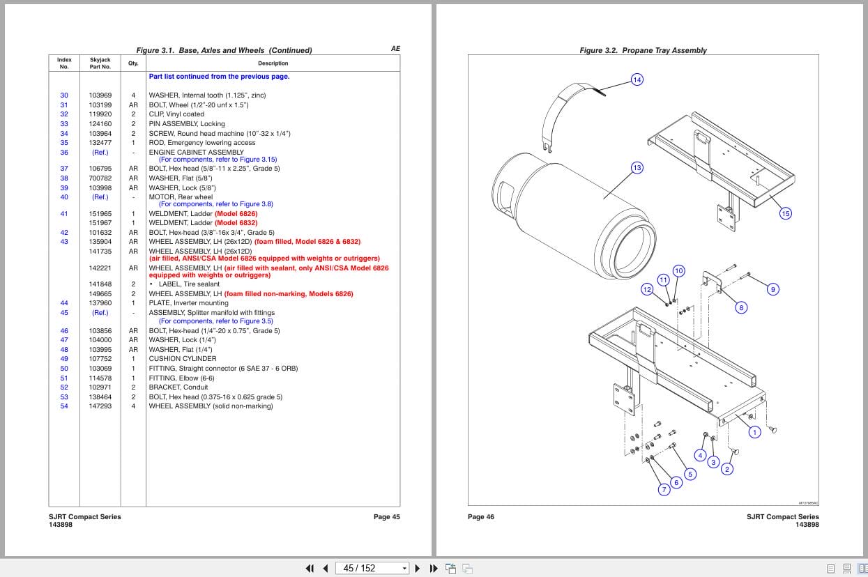
Figure 3.1. Base, Axles and Wheels
Figure 3.2. Propane Tray Assembly
Figure 3.3. Steer Cylinder Assembly with Hardware
Figure 3.4. Tie Rod Assembly with Hardware
Figure 3.5. Splitter Manifold
Figure 3.6. Splitter Manifold Plumbing
Figure 3.7. Front Wheel Motor
Figure 3.8. Rear Wheel Motor
Figure 3.9. Main Manifold Plumbing
Figure 3.10. Hydraulic Cabinet Assembly
Figure 3.11. Oil Tank Assembly
Figure 3.12. Gas Tank Assembly
Figure 3.13. Main Manifold
Figure 3.14. Hydraulic Door Assembly
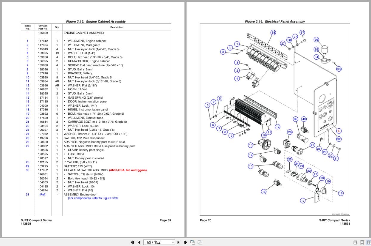
Figure 3.15. Engine Cabinet Assembly
Figure 3.16. Electrical Panel Assembly
Figure 3.17. Engine Installation (Kubota DF972)
Figure 3.18. Engine Installation (Kubota D902)
Figure 3.19. Tray Engine Assembly
Figure 3.20. Engine Door Assembly
Figure 3.21. Engine and Main Manifold Harness Diagrams
Figure 3.22. Electrical Panel Harness Diagram
Figure 3.23. Load Sensing Components
Engines And Related Parts
Figure 4.1. Engine Assembly (Kubota Engine DF972)
Figure 4.2. Air Cleaner Assembly – Kubota Dual Fuel Engine DF972
Figure 4.3. Exhaust System Assembly – Kubota Engines DF972 / D902
Figure 4.4. Radiator Kit – Kubota DF972 / D902
Figure 4.5. Hydraulic Pump Assembly (Kubota Engine DF972 / D902)
Figure 4.6. Propane Fuel System – Kubota Dual Fuel Engine DF972
Figure 4.7. Propane Fuel System – Dual Tank (Kubota Engine DF972)
Figure 4.8. Engine Assembly (Kubota Engine D902)
Figure 4.9. Air Cleaner Assembly (Kubota Engine D902)
Optional Equipment
Figure 5.1. Outrigger Control Box Assembly
Figure 5.2. Outrigger Electrical Connections
Figure 5.3. GP-108 Controller
Figure 5.4. Flashing Light Relay Harness
Figure 5.5. Front And Rear Outrigger Assembly
Figure 5.6. Outrigger Assembly
Figure 5.7. Outrigger Cylinder Assembly
Figure 5.8. Outrigger Hydraulic Connections
Figure 5.9. Outrigger Manifold Assembly
Figure 5.10. 800W Inverter Option
Figure 5.11. 110/220 Clamp Assembly Option
Figure 5.12. Hydraulic Generator Option
Figure 5.13. Hydraulic Hose Connection – Hydraulic Generator Option
Figure 5.14. Hydraulic Generator Relay Assembly
Figure 5.15. Scissor Guard Option With Diesel Fuel
Figure 5.16. Scissor Guard With Dual Fuel
Figure 5.17. Work Light Option
Labels And Nameplate
Figure 6.1. Label Kit
Figure 6.2. Labels – Chassis (Left and Back)
Figure 6.3. Labels – Chassis (Front and Right)
Figure 6.4. Labels – Chassis (Top)
Figure 6.5. Labels – Misc
Figure 6.6. Labels – Misc
Tables
Table 1.1. SJRT Scissor Fluids
Related Products
-
Skyjack Vertical Mast Lifts SJ20 Service Manual 238886ADA 2023
20 USDSize: 9.74 MBFormat: PDFLanguage: EnglishBrand: SkyjackType of Machine: Vertical Mast LiftsType of Manual: Service Manual, Electrical SchematicModel: Skyjack SJ20 Vertical Mast LiftsSerial Number: A601000001 to A601000905Part Number: 238886ADAPublication Date: 2023Number of Pages: 158 Pages
REALEASE :
REALEASE :
-
Skyjack Vertical Mast Lifts SJ12E SJ16E SJ20E Parts Manual 241913ADA 2023
15 USDSize: 7.44 MBFormat: PDFLanguage: EnglishBrand: SkyjackType of Machine: Vertical Mast LiftsType of Manual: Parts ManualModel: Skyjack SJ12E, SJ16E, SJ20E Vertical Mast LiftsSerial Number: A601000906 – A601999999Part Number: 241913ADAPublication Date: 2023Number of Pages: 138 Pages
REALEASE :
REALEASE :
-
Skyjack Vertical Mast Lifts SJ20 Parts Manual 238885ACA 2023
15 USDSize: 6.43 MBFormat: PDFLanguage: EnglishBrand: SkyjackType of Machine: Vertical Mast LiftsType of Manual: Parts ManualModel: Skyjack SJ20 Vertical Mast LiftsSerial Number: A601000001 to A601000905Part Number: 238885ACAPublication Date: 2023Number of Pages: 116 Pages
REALEASE :
REALEASE :
-
Skyjack Vertical Mast Lifts SJ12E SJ16E SJ20E Operating Manual 243762ABA 2022
10 USDSize: 5.67 MBFormat: PDFLanguage: EnglishBrand: SkyjackType of Machine: Vertical Mast LiftsType of Manual: Operating ManualModel: Skyjack SJ12E, SJ16E, SJ20E Vertical Mast LiftsSerial Number: A601001639 & abovePart Number: 243762ABAPublication Date: 2022Number of Pages: 92 Pages
REALEASE :
REALEASE :
-
Skyjack Vertical Mast Lifts SJ12E SJ16E SJ20E Service Manual 241914ADA 2023
20 USDSize: 10.70 MBFormat: PDFLanguage: EnglishBrand: SkyjackType of Machine: Vertical Mast LiftsType of Manual: Service Manual, Electrical SchematicModel: Skyjack SJ12E, SJ16E, SJ20E Vertical Mast LiftsSerial Number: A601000906 – A601999999Part Number: 241914ADAPublication Date: 2023Number of Pages: 154 Pages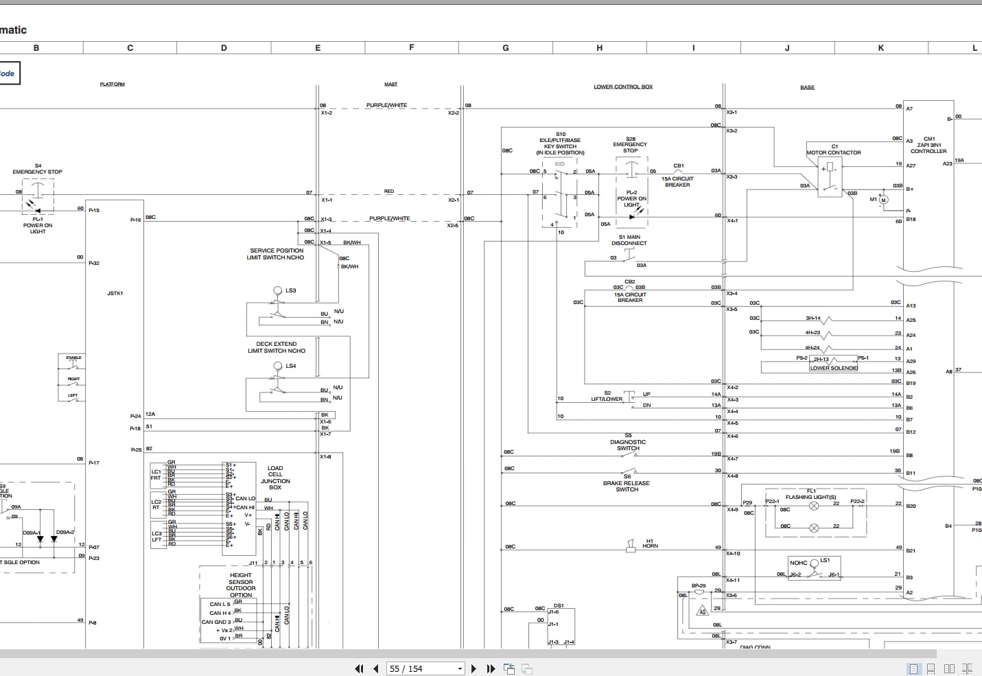
REALEASE :
REALEASE :
-
Skyjack Vertical Mast Lifts SJ20 Operating Manual 236504AFA 2022
10 USDSize: 5.17 MBFormat: PDFLanguage: EnglishBrand: SkyjackType of Machine: Vertical Mast LiftsType of Manual: Operating ManualModel: Skyjack SJ20 Vertical Mast LiftsSerial Number: A601000001 – A601000905Part Number: 236504AFAPublication Date: 2022Number of Pages: 94 Pages
REALEASE :
REALEASE :
-
Skyjack NA 4.93GB PDF Operating Parts Service Manuals
Original price was: 200.140Current price is: 140. USDThis is a service information package, you will need to use this to repair a vehicleHot-30%
REALEASE :
REALEASE :
-
Skyjack Lift Aerial Working Platform AWP All Models 2020 Documentation PDF DVD
Original price was: 200.110Current price is: 110. USDSkyjack Lift Aerial Working Platform AWP All Models 2020 Documentation PDF DVDSize: 6.39 GBFormat: PDFLanguage: EnglishBrand: Skyjack LiftAmount of DVD: 1 DVDWindow: All Window 32 & 64 bit, Mac OSType of Vehicle: Aerial working platform (AWP)Type of Document: Operating – Parts – Service Manuals PDFHot-45%
REALEASE :
30.05.2020
REALEASE :
30.05.2020