
15 ITEMSVIEW CART


Total: 2,273.00


Expert Support
Full Speed
100% Working
20 USD
Contents:
Section 1 – Scheduled Maintenance
1.1 Read and Heed
1.2 Maintenance and Inspection Schedule
1.3 Hydraulic System & Component Maintenance and Repair
1.4 About this Section
1.5 Owner’s Annual Inspection Record
1.6 Scheduled Maintenance Inspections
1.7 Function Tests
Section 2 – Specifications
2.1 Specifications and Features
2.2 Floor Load Calculation
2.4 Floor Loading Pressure
2.3 Maximum Platform Capacities
2.5 Fluid Specifications
2.6 Torque Specifications
2.7 Torque Specifications for Fasteners (Imperial)
2.8 Torque Specifications for Fasteners (Metric)
2.9 Torque Specifications for Hydraulic Couplings & Hoses
Section 3 – System Component Identification and Schematics
3.1 Hydraulic Symbol Chart
3.2 Electrical Symbol Chart
3.3 AC Cord Color Code
3.4 Hydraulic Schematic Parts List
3.5 Electrical Parts List
3.6 Hydraulic Schematic S/N 37006450 and above
3.7 Hydraulic Schematic S/N 37006449 and below
3.8 Hydraulic Manifold Valve Port Identification
3.9 Hydraulic Manifold Valve Assemblies and Port Identification
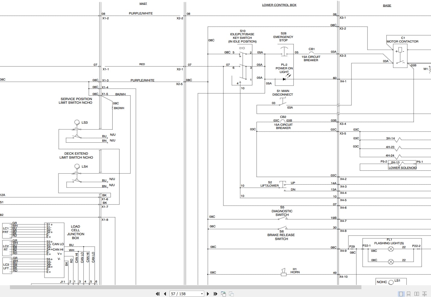
3.10 Control Box Wiring Diagram
3.11 Outrigger / Hydraulic Generator Control Console Wiring Diagram
3.12 Scissor Arm Control Cable Wiring Diagram
3.13 Main Manifold Valve Harness Wiring Diagram
3.14 Kubota Engine Wiring Diagram – Dual Fuel System – S/N 37009728 and Below
3.15 Kubota Engine Wiring Diagram – Dual Fuel System – S/N 37009729 and Above
3.16 Kubota Engine Wiring Diagram (Diesel Fuel System)
3.17 Outrigger Harness Wiring Diagram
3.18 Hydraulic Generator Electrical Panel Assembly
3.19 All Motion Alarm Electrical Panel Diagram
3.20 Telematics Harness Wiring Diagram
3.21 Flashing Light Relay Harness
3.22 Electrical Panel Wiring Diagram S/N 37000235 and above
3.23 Electrical Panel Wiring Diagram S/N 37000234 and below
3.24 Electrical Panel Diagram with Positive Air Shut Off Option S/N 37000235 and above
3.25 Electrical Panel Diagram with Positive Air Shut Off Option S/N 37000234 and below
3.26 Positive Air Shut Off Harness Wiring Diagram – Diesel Engine
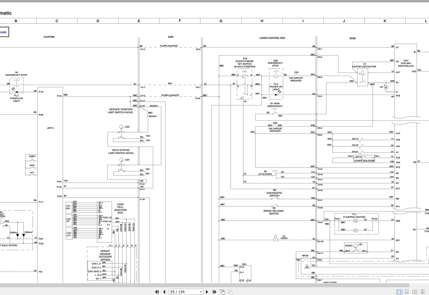
3.27 Electrical Schematic (No Option with Kubota Dual Fuel Engine) S/N 37009565 and above
3.28 Electrical Schematic (No Option with Kubota Dual Fuel Engine) S/N 37000235 to 37009564
3.29 Electrical Schematic (No Option with Kubota Dual Fuel Engine) S/N 37000234 and below
3.30 Electrical Schematic (All Option with Kubota Dual Fuel Engine) S/N 37009565 and above
3.31 Electrical Schematic (All Option with Kubota Dual Fuel Engine) S/N 37000235 to 37009564
3.32 Electrical Schematic (All Option with Kubota Dual Fuel Engine) S/N 37000234 and below
3.33 Electrical Schematic (All Option with Kubota Diesel Engine) S/N 37000235 and above
3.34 Electrical Schematic (All Option with Kubota Diesel Engine) S/N 37000234 and below
Section 4 – Troubleshooting Guide
4.1 Introduction
4.2 Electrical System
4.3 Hydarulic System
Section 5 – Service Procedures
5.1 General
5.2 Platform
5.3 Scissors
5.4 Engine
5.5 Base
5.6 Hydraulics
5.7 Drive Circuit Flush Procedure
5.8 Drive Pressure and Wheel Motor Tests
5.9 Outriggers
5.10 EZcal Diagnostic Tool
5.11 OCM1 Control Module
5.12 GP-106 Control Module
5.13 GP-108 Control Module
REALEASE :
REALEASE :
REALEASE :
REALEASE :
REALEASE :
REALEASE :
REALEASE :
REALEASE :

REALEASE :
30.05.2020
REALEASE :
30.05.2020

REALEASE :
REALEASE :
REALEASE :
REALEASE :
REALEASE :
REALEASE :
 Automotive - Heavy Equipment - Truck & Bus - Forklift - Crane