
9 ITEMSVIEW CART


Total: 872.00
Expert Support
Full Speed
100% Working
20 USD
Contents:
Section 1 – Maintenance
1.1 Read and heed
1.2 General Information
1.3 Scheduled maintenance and inspections
Section 2 – Maintenance Tables and Diagrams
2.1 Standard hose numbering system
2.2 Torque specifications for fasteners (metric)
2.3 Torque specifications for fasteners (US imperial)
2.4 Torque specifications for hydraulic couplings & hoses
2.5 MEWP torque specifications
2.6 Specifications and features
2.7 Fluids
2.8 Maximum platform capacities (evenly distributed)
Section 3 – System Component Identification and Schematics
3.1 Electrical Symbol Chart
3.2 Hydraulic Symbol Chart
3.3 Wire Number and Color Chart
3.4 Hydraulic Parts List
3.5 Electrical Parts List
3.6 Major Component Identification
3.7 Hydraulic Manifold Valve Port Identification
3.8 Hydraulic Manifold Valve Assemblies and Port
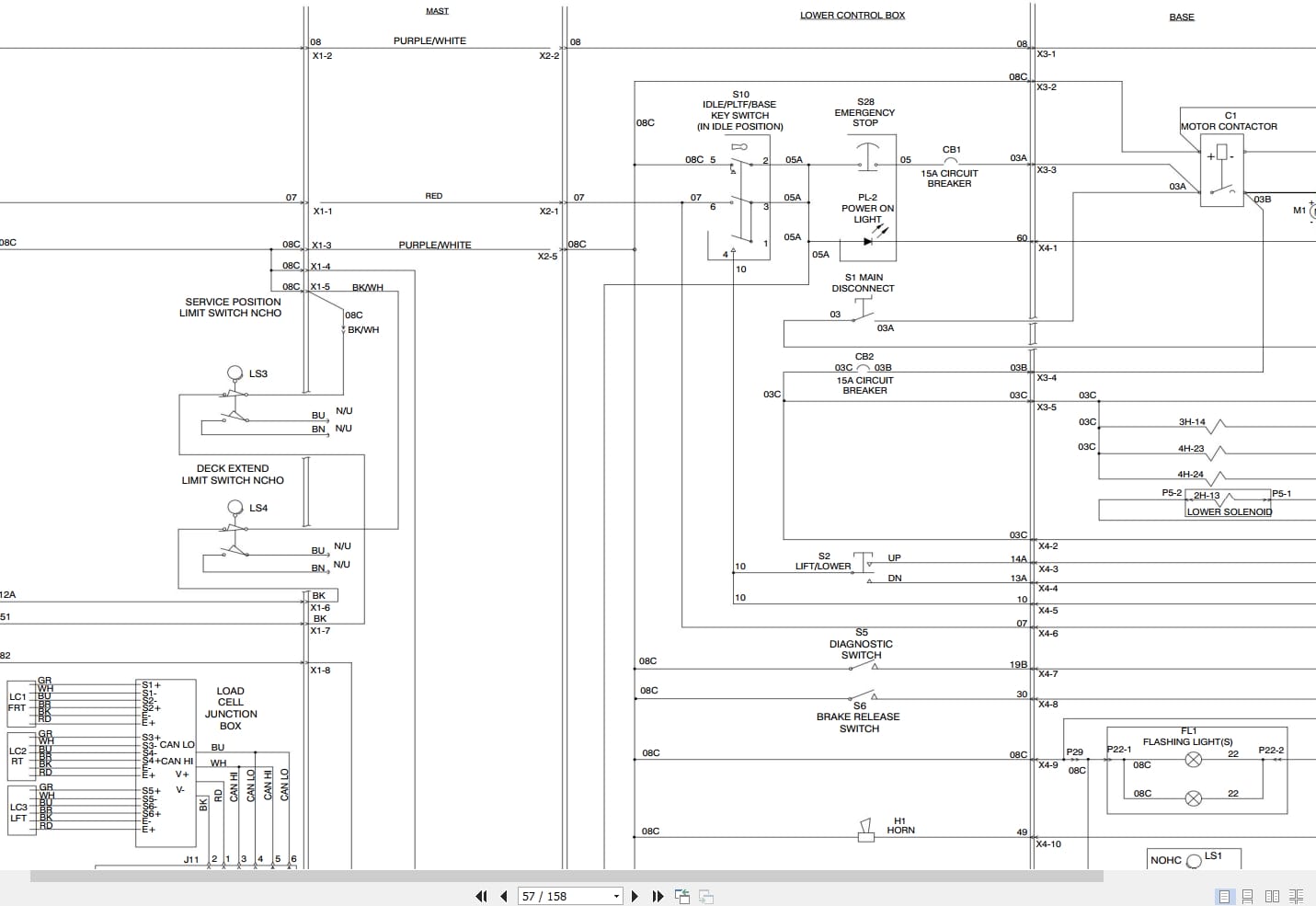
3.9 Control Box Wiring Diagram
3.10 Base to Platform Control Cable – SJ6832 RT
3.11 Base to Platform Control Cable – SJ6826 RT
3.12 Beeper Wiring Assembly
3.13 Main Manifold Valve Harness Wiring Diagram
3.14 Elevate Telematics Harness
3.15 Kubota Engine Harness – Diesel
3.16 Kubota Engine Harness – Dual Fuel
3.17 Outrigger Control Box
3.18 Outrigger/Hydraulic Generator Control Box
3.19 Hydraulic Generator Electrical Panel Assembly
3.20 Telematic Harness Wiring Diagram
3.21 Flashing Light Relay Harness
3.22 Pressure Transducer Harness
3.23 Transducer Harness
3.24 Outrigger Electrical Assembly
3.25 Outrigger/Hydraulic Generator Electrical Assembly
3.26 Electrical Panel Diagram – ANSI/CSA, CE & AS
3.27 Electrical Panel Diagram – KC
3.28 Electrical Panel Diagram – Positive Air Shut-Off
3.29 Electrical Panel Diagram – Soft Stop
3.30 Hydraulic Schematic – ANSI/CSA
3.31 Hydraulic Schematic – CE/AS
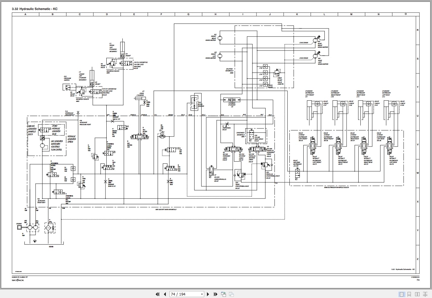
3.32 Hydraulic Schematic – KC
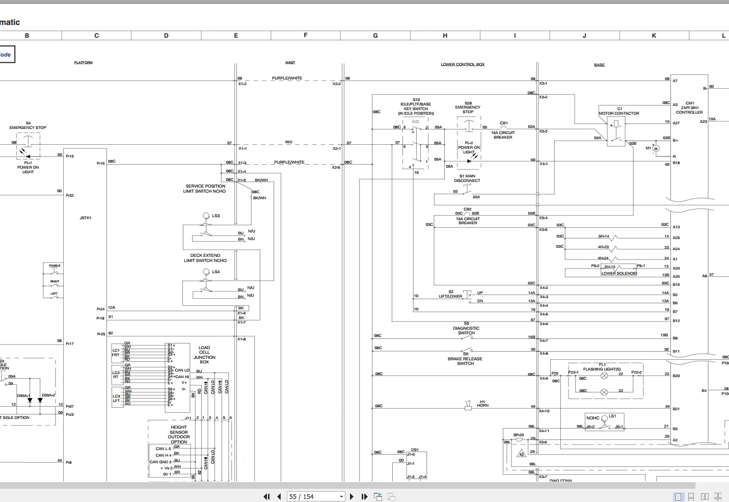
3.33 Electrical Schematic – Kubota Dual Fuel WG752 – ANSI/CSA
3.34 Electrical Schematic – Kubota Dual Fuel WG752 – ANSI/CSA – No Options
3.35 Electrical Schematic – Kubota Diesel D902 – ANSI/CSA
3.36 Electrical Schematic – Kubota Diesel D902 – ANSI/CSA – No Options
3.37 Electrical Schematic – Kubota Diesel D902- CE
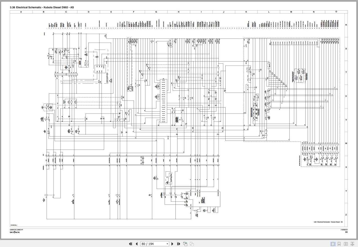
3.38 Electrical Schematic – Kubota Diesel D902 – AS
3.39 Electrical Schematic – Kubota Diesel D902 – AS/CE – No Options
Section 4 – Troubleshooting Information
4.1 Introduction
4.2 Electrical System
4.3 Hydraulic Systems
Section 5 – Procedures
5.1 General
5.2 Platform
5.3 Scissors
5.4 Engine
5.5 Base
5.6 Hydraulics
5.7 Drive Circuit Flush Procedure
5.8 Drive Pressure and Wheel Motor Tests
5.9 Outriggers
5.10 Control Modules Identification and Locations
5.11 EZcal Diagnostic Tool
5.12 OCM1 Control Module
5.13 GP-102 Control Module
5.14 GP-106 Control Module
5.15 GP-108 Control Module
REALEASE :
REALEASE :
REALEASE :
REALEASE :
REALEASE :
REALEASE :

REALEASE :
30.05.2020
REALEASE :
30.05.2020
REALEASE :
REALEASE :
REALEASE :
REALEASE :

REALEASE :
REALEASE :
REALEASE :
REALEASE :
 Automotive - Heavy Equipment - Truck & Bus - Forklift - Crane