
1 ITEMVIEW CART

Total: 160.00
Expert Support
Full Speed
100% Working
20 USD
Contents:
Section 1 – Scheduled Maintenance
1.1 Read and Heed
1.2 Maintenance and Inspection Schedule
1.3 Hydraulic System & Component Maintenance and Repair
1.4 Scheduled Maintenance
1.5 Owner’s Annual Inspection Record
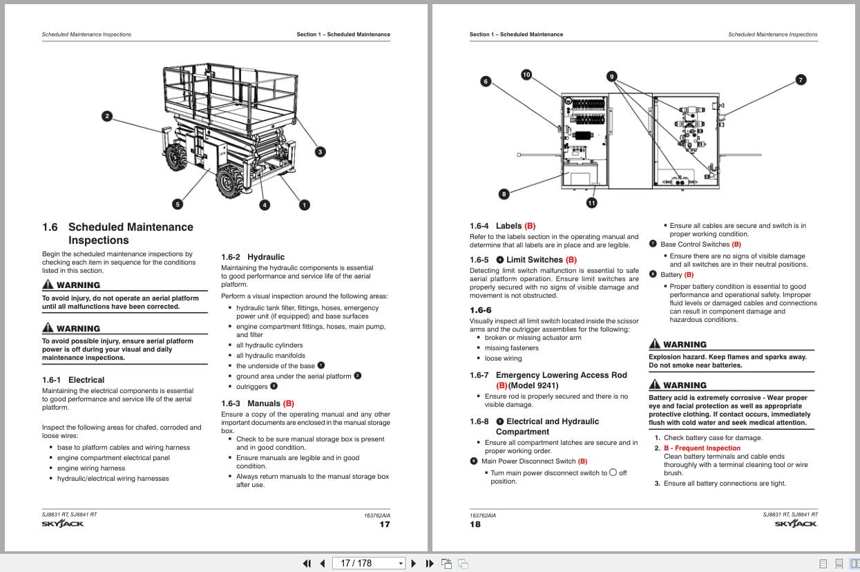
1.6 Scheduled Maintenance Inspections
Section 2 – Maintenance Tables and Diagrams
2.1 Specifications and Features
2.2 Maximum Platform Capacities (Evenly Distributed)
2.3 Floor Loading Pressure
2.4 Tire Specifications
2.5 Fluids
2.6 Torque Specifications
2.7 Torque Specifications for Fasteners (Imperial)
2.8 Torque Specifications for Fasteners (Metric)
2.9 Torque Specifications for Hydraulic Couplings and Hoses
Section 3 – System Component Identification and Schematics
3.1 Electrical Symbol Chart
3.2 Hydraulic Symbol Chart
3.3 AC Cord Color Code
3.4 Hydraulic Parts List
3.5 Electrical Parts List
3.6 Platform Control Console Diagram with All Options (ANSI/CSA)
3.7 Control Cable Assemblies Diagram
3.8 Outrigger/Hydraulic Generator Control Console Wiring
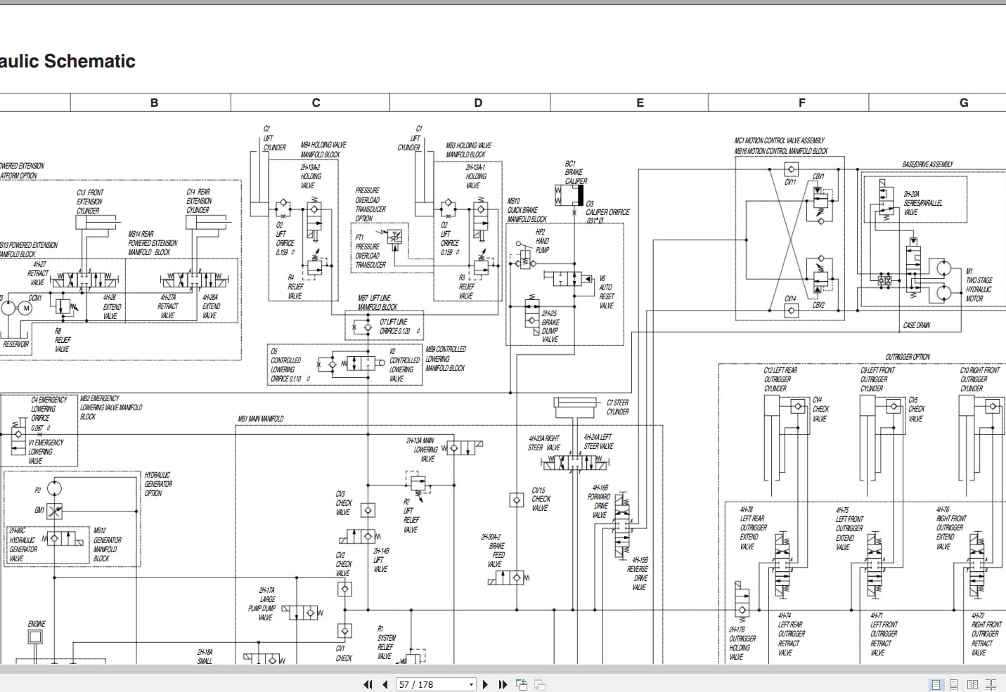
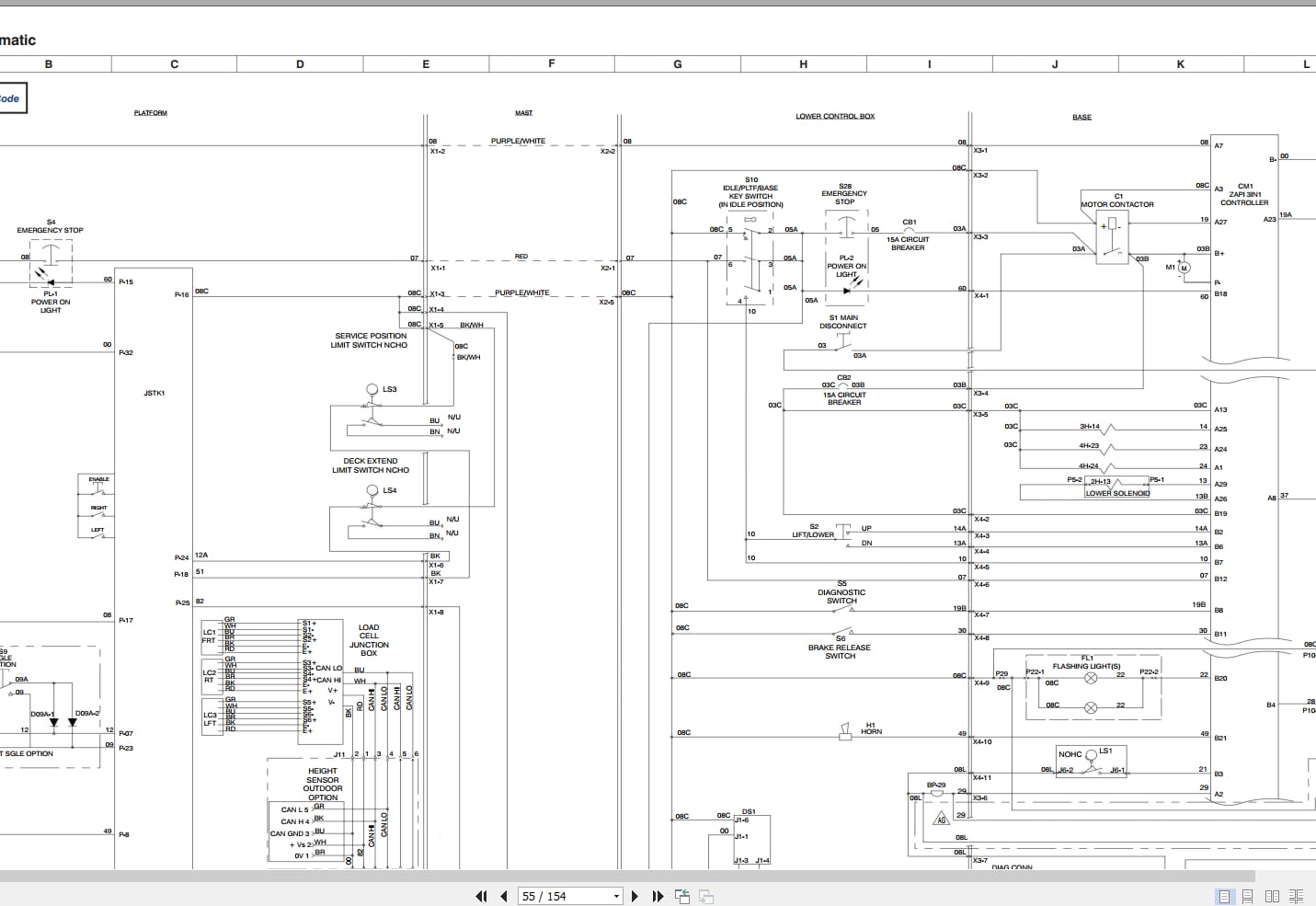
3.9 Hydraulic Schematic
3.10 Main Manifold Components and Port Identifications
3.11 Hydraulic Manifold Components and Port Identifications
3.12 Main Manifold Wiring Diagram (ANSI/CSA)
3.13 Horn, Light, Beeper Wiring Diagram (ANSI/CSA)
3.14 Powered Extension Platform – Electrical Connection Diagram
3.15 Electrical Panel Diagram – 12 kW Generator Modification (ANSI/CSA)
3.16 12 kW Generator Hydraulic and Electric Wiring Schematics (ANSI/CSA)
3.17 Electrical Panel Diagram – Outrigger Option
3.18 Engine Interface Harness Wiring Diagram – Kubota Dual Fuel Engine (DF972 EFI)
3.19 Engine Interface Harness Schematic – Kubota DF 972
3.20 Engine Interface Electrical Schematic – Kubota Dual Fuel Engine (DF972 EFI)
3.21 Telematics Harness Wiring Diagram
3.22 Flashing Light Relay Harness
3.23 Engine Harness Wiring Diagram – Kubota Diesel Engine
3.24 Engine Harness Wiring Diagram – Kubota Dual Fuel Engine
3.25 Electrical Panel Diagram (ANSI/CSA)
3.26 Electrical Panel Diagram (ANSI/CSA)
3.27 Electrical Panel Diagram with Positive Air Shutoff Option
3.28 Electrical Panel Diagram with Positive Air Shutoff Option
3.29 Positive Air Shutoff Harness Wiring Diagram – Diesel Engine
3.30 Electrical Schematic – Dual Fuel – No Options (ANSI/CSA)
3.31 Electrical Schematic – Dual Fuel – No Options (ANSI/CSA)
3.32 Electrical Schematic – Dual Fuel – No Options (ANSI/CSA)
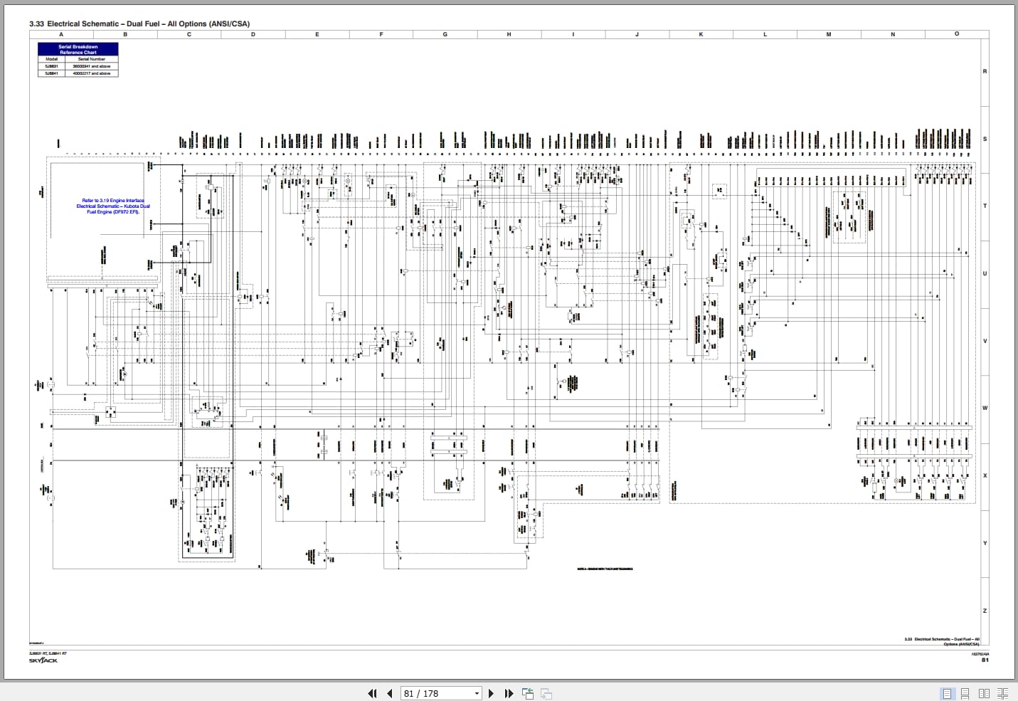
3.33 Electrical Schematic – Dual Fuel – All Options (ANSI/CSA)
3.34 Electrical Schematic – Dual Fuel – All Options (ANSI/CSA)
3.35 Electrical Schematic – Dual Fuel – All Options (ANSI/CSA)
3.36 Electrical Schematic – Diesel – All Options (ANSI/CSA)
3.37 Electrical Schematic – Diesel – All Options (ANSI/CSA)
3.38 Outrigger Wiring Diagram
3.39 Electrical Panel Diagram – Oil Cooler Option
3.40 Hydraulic Generator Electrical Panel Diagram – Kubota Engine (ANSI/CSA)
Section 4 – Troubleshooting Information
4.1 Introduction
4.2 Electrical System
4.3 Hydraulic System
Section 5 – Procedures
5.1 General
5.2 Platform
5.3 Scissors
5.4 Engines
5.5 Base
5.6 Hydraulics
5.7 Outriggers
5.8 Control Modules Identification and Locations
5.9 EZcal Diagnostic Tool
5.10 OCM1 Control Module
5.11 GP-106 Control Module
5.12 GP-108 Control Module
REALEASE :
REALEASE :
REALEASE :
REALEASE :

REALEASE :
REALEASE :

REALEASE :
30.05.2020
REALEASE :
30.05.2020
REALEASE :
REALEASE :
REALEASE :
REALEASE :
REALEASE :
REALEASE :
REALEASE :
REALEASE :
 Automotive - Heavy Equipment - Truck & Bus - Forklift - Crane