
2 ITEMSVIEW CART


Total: 60.00


Expert Support
Full Speed
100% Working
15 USD
Contents:
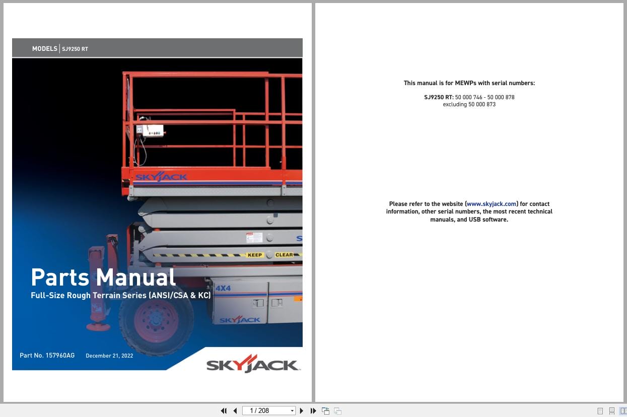
1.0 Platform Related Parts
1.1 Platform and Hinged Railing Assembly
1.2 Gate Latch Assembly
1.3 Powered Extension Platform Assembly
1.4 Quick Release Pin Assemblies
1.5 Powered Extension Cylinder Mounting Assembly
1.6 Powered Extension Cylinder Assembly
1.7 Powered Extension Power Unit Assembly
1.8 Platform Extension Platform Control Console
1.9 Electrical Panel Connection – Platform Extension (ANSI/CSA)
1.10 Electrical Panel Connection – Platform Extension (KC)
1.11 Safety D-Ring Assembly
1.12 Hydraulic Hose Connection – Single Powered Extension Cylinder
1.13 Hydraulic Hose Connection – Dual Powered Extension Cylinders
1.14 Platform Control Console Assembly – Hardware
1.15 Platform Control Console Assembly – Switches
1.16a Drive/Steer Controller Assembly
1.16b Drive/Steer Controller Assembly
2.0 Scissor Related Parts
2.1 Scissor Assembly
2.2 Scissor Arm Mounting Hardware
2.3 Scissor Arm Connecting Hardware
2.4 Hydraulic Hose Connection – Lift Cylinders
2.5 Lift Cylinder Assembly
2.6 Holding Valve Assembly
2.7 Holding Valve Assembly with Pressure Switch (KC)
2.8 Electrical Connection – Scissor Assembly
2.9 Horn, Light and Beeper Assembly (ANSI/CSA)
2.10 Beeper Assembly (KC)
2.11 Scissor Control Cable Assembly
3.0 Base Related Parts
3.1 Base Assembly
3.2 Fuel Cabinet Assembly
3.3 Fuel Tank Assembly
3.4 Hydraulic/Electrical Cabinet Assembly
3.5 Hydraulic Oil Tank Assembly
3.6 Hydraulic Hose Connections – Base with Linamar Axles
3.7 Hydraulic Hose Connections – Base with Dana Axles (ANSI/CSA)
3.8 Hydraulic Hose Connections – Hydraulic Cabinet
3.9 Cushion Valve Assembly
3.10 Emergency Lowering Valve Assembly
3.11 Electrical Connections – Emergency Lowering (ANSI/CSA)
3.12 Electrical Connections – Emergency Lowering & Platform Retraction (KC)
3.13 Brake Cylinder Assembly
3.14 Motion Control Valve Assembly
3.15 Auto Reset Brake Manifold Assembly (Linamar Axles)
3.16 Main Manifold Assembly
3.17 Electrical Panel Assembly
3.18 Electrical Harnesses
3.19 Base Controls Assembly
4.0 Axle Related Parts
4.1 Front Idle Arm Assembly – 2 Wheel Drive (ANSI/CSA)
4.2 Linamar Front Axle Hardware Assembly – All Wheel Drive
4.3 Linamar Front Axle Assembly – All Wheel Drive
4.4 Linamar Front Axle End Assembly – All Wheel Drive
4.5 Linamar Front Axle Differential Assembly – All Wheel Drive
4.6 Wheel Hub Assembly – All Wheel Drive (Linamar Axle)
4.7 Linamar Front Axle Shaft Assembly – All Wheel Drive
4.8 Linamar Front Axle Steer Cylinder Assembly
4.9 Dana Front Axle Assembly – All Wheel Drive (ANSI/CSA)
4.10 Dana Front Axle Drive Assembly – All Wheel Drive (ANSI/CSA)
4.11 Dana Steer Cylinder Assembly
4.12 Drive Shaft Assembly
4.13 Drive Motor Assembly
4.14 Center Drive Assembly
4.15 Linamar Rear Axle Assembly
4.16 Linamar Rear Axle Differential Assembly
4.17 Linamar Rear Axle Brake Assembly
4.18 Dana Rear Axle Drive Assembly
5.0 Engine Related Parts
5.1 Engine Roll-Out Tray Assembly (Kubota Engine)
5.2 Engine Control Panel
5.3 Kubota Diesel Engine Assembly (D1305)
5.4 Kubota Diesel Fuel System (D1305)
5.5 Kubota Diesel Engine Harness
5.6 Air Intake Assembly (Kubota Diesel Engine D1305)
5.7 Exhaust Manifold Assembly (Kubota Diesel Engine D1305)
5.8 Hydraulic Pump Assembly
5.9 Engine Roll-Out Tray Assembly (GM Engine)
5.10 GM Dual Fuel Engine Assembly
5.11 Bell Housing Assembly (GM Engine)
5.12 Engine Interface Harness (GM Engine)
5.13 Hose Connections – GM Dual Fuel Engine
6.0 Optional Equipment
6.1 Electrical Panel Connections – Hydraulic Outrigger
6.2 Hydraulic Hose Connections – Hydraulic Outrigger
6.3 Outrigger Assembly
6.4 Outrigger Cylinder Assembly
6.5 Outrigger Manifold Assembly
6.6 Outrigger/Hydraulic Generator Control Console Assembly
6.7 3500W Generator and Oil Cooler Assembly
6.8 Hydraulic Hose Connections – 3500W Hydraulic Generator
6.9 1500W Inverter Assembly
6.10 Work Light Option
6.11 Air Hose to Platform Option
6.12 Platform AC Outlet Assembly
6.13 GP-108 Controller
6.14 Flashing Light Relay Harness
7.0 Labels
7.1 Label Kits
7.2 Labels – Control Consoles
7.3 Labels – Miscellaneous
7.4 Labels – Left Side View
7.5 Labels – Right Side View
7.6 Labels – Front and Rear View
7.7 Labels – Hydraulic Outriggers
8.0 Tables
8.1 Fluid Tables
REALEASE :
REALEASE :

REALEASE :
REALEASE :
REALEASE :
REALEASE :
REALEASE :
REALEASE :
REALEASE :
REALEASE :
REALEASE :
REALEASE :
REALEASE :
REALEASE :

REALEASE :
30.05.2020
REALEASE :
30.05.2020
 Automotive - Heavy Equipment - Truck & Bus - Forklift - Crane