
0 ITEMSVIEW CART


✓
Expert Support
✓
Full Speed
✓
100% Working
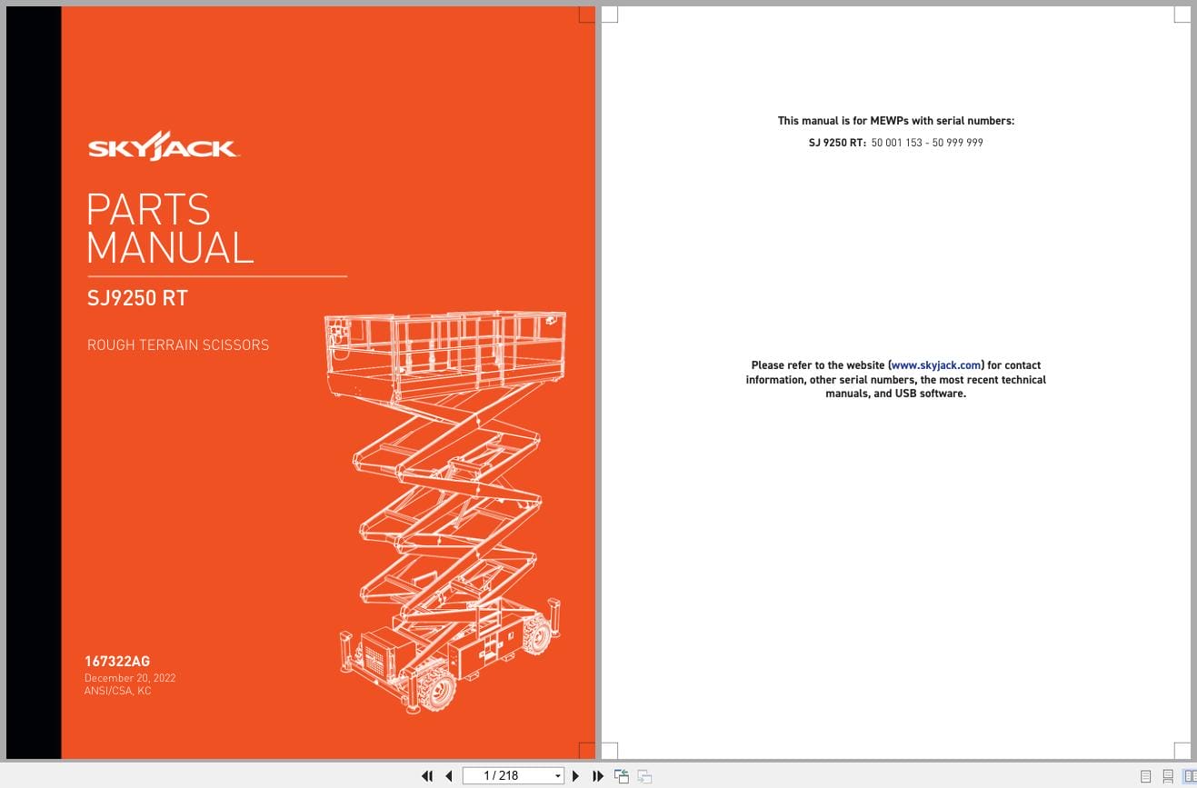
Skyjack Rough Terrain Scissors SJ9250RT Parts Manual 167322AG 2022
Size: 11.38 MB
Format: PDF
Language: English
Brand: Skyjack
Type of Machine: Rough Terrain Scissors
Type of Manual: Parts Manual
Model: Skyjack SJ9250RT Rough Terrain Scissors
Serial Number: 50001153 – 50999999
Part Number: 167322AG
Publication Date: 2022
Number of Pages: 218 Pages
15 USD
- Description
Description
Contents:
Foreword
General
Parts Ordering Information
Method of Listing
Quantities
How To Order Repair Parts
Section 1 – Platform Related Parts
1.1 Platform and Hinged Railing Assembly
1.2 Gate Latch Assembly
1.3 Safety D-Ring Assembly
1.4 Powered Extension Platform Assembly
1.5 Quick Release Pin Assemblies
1.6 Powered Extension Cylinder Mounting Assemblies
1.7 Powered Extension Cylinder Assembly
1.8 Powered Extension Power Unit Assembly A
1.9 Powered Extension Power Unit Assembly B
1.10 Power Unit Assembly – Single Extension
1.11 Power Unit Assembly – Double Extension
1.12 Platform Extension Platform Control Console
1.13 Electrical Panel Connection – Platform Extension (ANSI/CSA)
1.14 Electrical Panel Connection – Platform Extension (KC)
1.15 Hydraulic Hose Connections – Single Powered Extension Cylinder A
1.16 Hydraulic Hose Connections – Single Powered Extension Cylinder B
1.17 Hydraulic Hose Connections – Dual Powered Extension Cylinders A
1.18 Hydraulic Hose Connections – Dual Powered Extension Cylinder B
1.19 Platform Control Console Assembly – Hardware
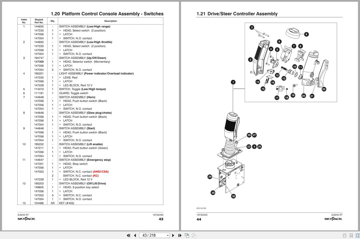
1.20 Platform Control Console Assembly – Switches
1.21 Drive/Steer Controller Assembly
1.22 Platform AC Outlet Assembly
Section 2 – Scissor Related Parts
2.1 Scissor Assembly
2.2 Scissor Arm Mounting Hardware
2.3 Scissor Arm Connecting Hardware
2.4 Hydraulic Hose Connection – Lift Cylinders
2.5 Lift Cylinder Assembly
2.6 Holding Valve Assembly
2.7 Holding Valve Assembly with Pressure Switch (KC)
2.8 Electrical Connection – Scissor Assembly
2.9 Horn, Light and Beeper Assembly (ANSI/CSA)
2.10 Horn, Light, Beeper and Transducer Assembly (KC)
2.11 Scissor Contol Cable Assembly
Section 3 – Base Related Parts
3.1 Base Assembly
3.2 Tire Assemblies
3.3 Fuel Cabinet Assembly
3.4 Fuel Tank Assembly
3.5 Hydraulic/Electrical Cabinet Assembly
3.6 Hydraulic Oil Tank Assembly
3.7 Hydraulic Hose Connections – Base
3.8 Hydraulic Hose Connections – Hydraulic Cabinet
3.9 Cushion Valve Assembly
3.10 Emergency Lowering Valve Assembly
3.11 Electrical Cabinet Components – Emergency Lowering and Powerdeck
3.12 Electrical Connections – Emergency Lowering (ANSI/CSA)
3.13 Electrical Connections – Emergency Lowering and Platform Retraction (KC)
3.14 Motion Control Valve Assembly
3.15 Auto Reset Brake Manifold Assembly
3.16 Main Manifold Assembly
3.17 Electrical Panel Assembly (ANSI/CSA)
3.18 Electrical Panel Assembly (KC)
3.19 GP-108 Controller
3.20 Flashing Light Relay Harness
3.21 Electrical Harnesses
3.22 Base Controls Assembly
3.23 Brake Release Pump with Lanyard
Section 4 – Axle Related Parts
4.1 Front Axle Assembly
4.2 Front Axle Hardware
4.3 Steer Cylinder Assembly
4.4 Drive Motor Assembly
4.5 Drive Shaft Assembly
4.6 Center Drive Assembly
4.7 Brake Caliper and Mount
4.8 Rear Axle Assembly
Section 5 – Engine Related Parts
5.1 Engine Roll-Out Tray Assembly
5.2 Engine Control Panel
5.3 Kubota Diesel Engine Assembly (D1305)
5.4 Kubota Diesel Fuel System (D1305)
5.5 Kubota Diesel Engine Harness
5.6 Air Intake Assembly (Kubota Diesel Engine D1305)
5.7 Exhaust Manifold Assembly (Kubota Diesel Engine D1305)
5.8 Hydraulic Pump Assembly A
5.9 Hydraulic Pump Assembly B
5.10 Kubota Dual Fuel Engine Assembly (DF972 EFI)
5.11 Radiator Kit – Kubota
5.12 Engine Harnesses (Kubota DF972 EFI Engine)
5.13 Air Intake Assembly (Kubota Dual Fuel Engine DF972 EFI)
5.14 Exhauset Assembly (Kubota Dual Fuel Engine DF9772 EFI)
5.15 Hose Connections (Kubota Dual Fuel Engine DF972 EFI)
5.16 Engine Display Assembly (Kubota Dual Fuel Engine DF972 EFI)
Section 6 – Optional Equipment
6.1 Electrical Panel Connections – Hydraulic Outrigger
6.2 Hydraulic Hose Connections – Hydraulic Outrigger
6.3 Outrigger Assembly
6.4 Outrigger Cylinder Assembly
6.5 Outrigger Manifold Assembly
6.6 Outrigger/Hydraulic Generator Control Console Assembly
6.7 3500 W Generator and Oil Cooler Assembly
6.8 Hydraulic Hose Connections – 3500 W Hydraulic Generator and Oil Cooler
6.9 Air Hose to Platform Option
6.10 Cold Start Option
6.11 Gate Hand Rail Kit
6.12 Telematics – ZTR
6.13 Positive Air Shut Off
6.14 Material Handling Stand
6.15 Tool Caddy Kit
6.16 Heavy Duty Pipe Rack
6.17 Elevate Telematics, Rework – Service Kit
6.18 Elevate Telematics, Ready – Service Kit
6.19 Secondary Guarding Lift Enable – Service Kit
Section 7 – Labels
7.1 Label Kits
7.2 Labels – Left and Right Sides
7.3 Labels – Front and Rear
7.4 Labels – Hydraulic Outriggers
7.5 Labels – Miscellaneous
7.6 Labels – Control Consoles
Section 8 – Tables
8.1 Fluids Table
Related Products
-
Skyjack Vertical Mast Lifts SJ12E SJ16E SJ20E Operating Manual 243762ABA 2022
10 USDSize: 5.67 MBFormat: PDFLanguage: EnglishBrand: SkyjackType of Machine: Vertical Mast LiftsType of Manual: Operating ManualModel: Skyjack SJ12E, SJ16E, SJ20E Vertical Mast LiftsSerial Number: A601001639 & abovePart Number: 243762ABAPublication Date: 2022Number of Pages: 92 Pages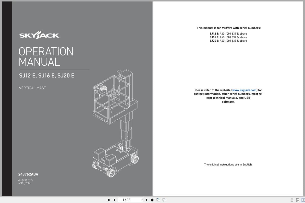
REALEASE :
REALEASE :
-
Skyjack NA 4.93GB PDF Operating Parts Service Manuals
Original price was: 200.140Current price is: 140. USDThis is a service information package, you will need to use this to repair a vehicleHot-30%
REALEASE :
REALEASE :
-
Skyjack Lift Aerial Working Platform AWP All Models 2020 Documentation PDF DVD
Original price was: 200.110Current price is: 110. USDSkyjack Lift Aerial Working Platform AWP All Models 2020 Documentation PDF DVDSize: 6.39 GBFormat: PDFLanguage: EnglishBrand: Skyjack LiftAmount of DVD: 1 DVDWindow: All Window 32 & 64 bit, Mac OSType of Vehicle: Aerial working platform (AWP)Type of Document: Operating – Parts – Service Manuals PDFHot-45%
REALEASE :
30.05.2020
REALEASE :
30.05.2020
-
Skyjack Vertical Mast Lifts SJ20 Parts Manual 238885ACA 2023
15 USDSize: 6.43 MBFormat: PDFLanguage: EnglishBrand: SkyjackType of Machine: Vertical Mast LiftsType of Manual: Parts ManualModel: Skyjack SJ20 Vertical Mast LiftsSerial Number: A601000001 to A601000905Part Number: 238885ACAPublication Date: 2023Number of Pages: 116 Pages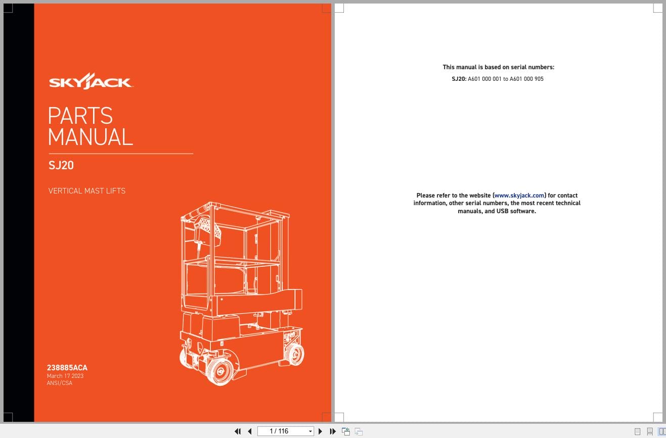
REALEASE :
REALEASE :
-
Skyjack Vertical Mast Lifts SJ12E SJ16E SJ20E Service Manual 241914ADA 2023
20 USDSize: 10.70 MBFormat: PDFLanguage: EnglishBrand: SkyjackType of Machine: Vertical Mast LiftsType of Manual: Service Manual, Electrical SchematicModel: Skyjack SJ12E, SJ16E, SJ20E Vertical Mast LiftsSerial Number: A601000906 – A601999999Part Number: 241914ADAPublication Date: 2023Number of Pages: 154 Pages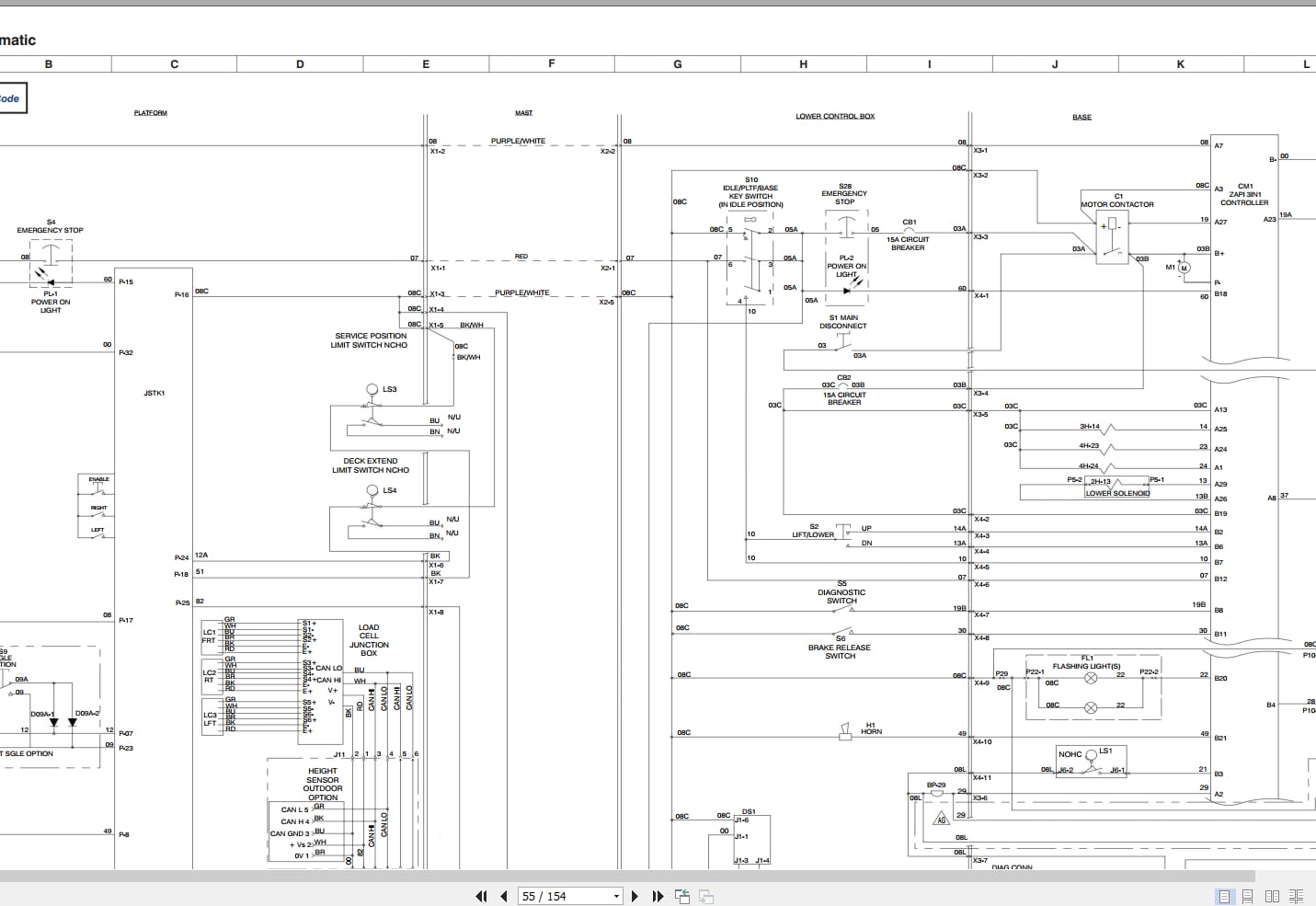
REALEASE :
REALEASE :
-
Skyjack Vertical Mast Lifts SJ20 Service Manual 238886ADA 2023
20 USDSize: 9.74 MBFormat: PDFLanguage: EnglishBrand: SkyjackType of Machine: Vertical Mast LiftsType of Manual: Service Manual, Electrical SchematicModel: Skyjack SJ20 Vertical Mast LiftsSerial Number: A601000001 to A601000905Part Number: 238886ADAPublication Date: 2023Number of Pages: 158 Pages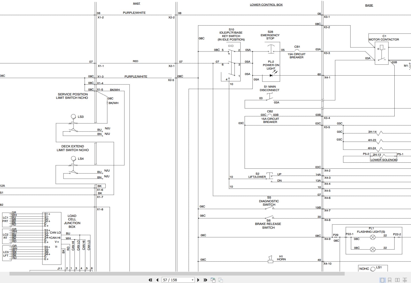
REALEASE :
REALEASE :
-
Skyjack Vertical Mast Lifts SJ20 Operating Manual 236504AFA 2022
10 USDSize: 5.17 MBFormat: PDFLanguage: EnglishBrand: SkyjackType of Machine: Vertical Mast LiftsType of Manual: Operating ManualModel: Skyjack SJ20 Vertical Mast LiftsSerial Number: A601000001 – A601000905Part Number: 236504AFAPublication Date: 2022Number of Pages: 94 Pages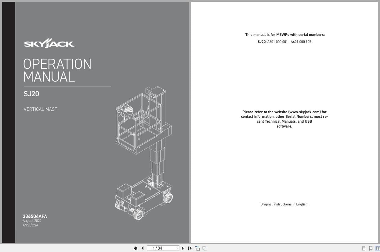
REALEASE :
REALEASE :
-
Skyjack Vertical Mast Lifts SJ12E SJ16E SJ20E Parts Manual 241913ADA 2023
15 USDSize: 7.44 MBFormat: PDFLanguage: EnglishBrand: SkyjackType of Machine: Vertical Mast LiftsType of Manual: Parts ManualModel: Skyjack SJ12E, SJ16E, SJ20E Vertical Mast LiftsSerial Number: A601000906 – A601999999Part Number: 241913ADAPublication Date: 2023Number of Pages: 138 Pages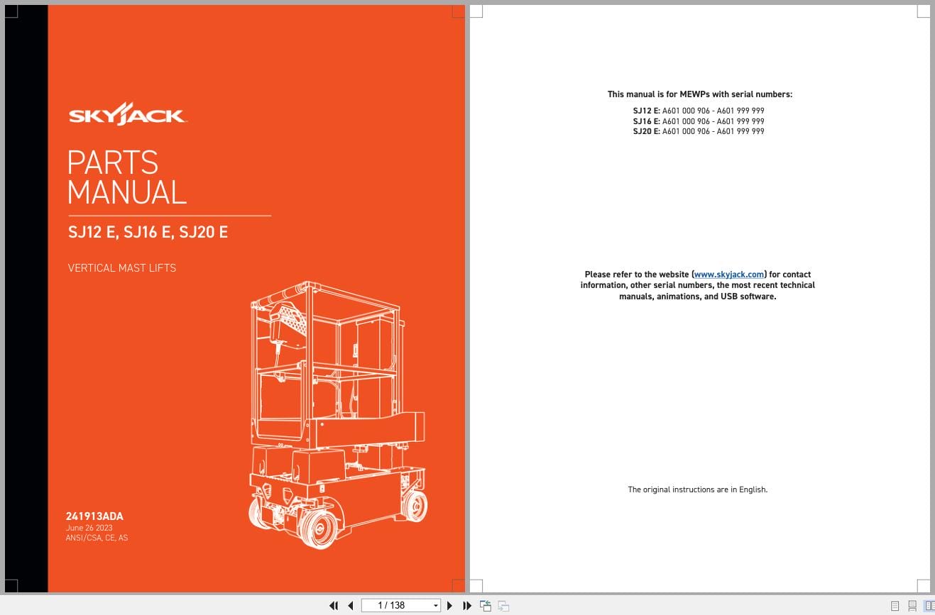
REALEASE :
REALEASE :