
0 ITEMSVIEW CART

✓
Expert Support
✓
Full Speed
✓
100% Working
Skyjack Telehandler SJ643TH SJ843TH Service Manual 230791AAA 2023
Size: 18.28 MB
Format: PDF
Language: English
Brand: Skyjack
Type of Machine: Telehandler
Type of Manual: Service Manual, Hydraulic Schematic, Electrical SChematic
Model: Skyjack SJ643TH, SJ843TH Telehandler
Serial Number: 87112758 & Above
Part Number: 230791AAA
Publication Date: 2023
Number of Pages: 172 Pages
20 USD
- Description
Description
Contents:
Section 1 – Scheduled Maintenance
1.1 Read and Heed
1.2 Maintenance and Inspection Schedule
1.3 Hydraulic System & Component Maintenance and Repair
1.4 About this Section
1.5 Scheduled Maintenance Inspections
1.6 Function Tests
Section 2 – Maintenance Tables
2.1 Standard and Optional Equipment
2.2 Specifications and Features
2.3 Tire/Wheel Specifications
2.4 Recommended Fluids/Lubrication
2.5 Pressure Setting
2.6 Standard Hose Numbering System
2.7 Torque Specifications for Fasteners (US)
2.8 Torque Specifications for Fasteners (Metric)
2.9 Torque Specifications for Hydraulic Couplings & Hoses
2.10 Air Conditioner Temperature/Pressure Chart
2.11 Floor loading pressure
Section 3 – System Component Identification and Schematics
3.1 Electrical Symbol Chart
3.2 Hydraulic Symbol Chart
3.3 Electrical Schematic Parts List
3.4 Hydraulic Schematic Parts List
3.5 Hydraulic Pump and Return Filter Ports Identification
3.6 Steering Control Unit Ports Identification
3.7 Service Brake Actuator (Brake Pedal) Ports Identification
3.8 Auxiliary Block Ports Identification
3.9 Joystick Port Identifications
3.10 Premium Joystick Port Identifications
3.11 Premium Joystick Manifold Port Identifications
3.12 Major Components Identification and Location
3.13 Main Control Valve Port Identification
3.14 Enclosed Cab Harness & Wiring Diagram
3.15 Glow Plug Harness & Wiring Diagram
3.16 Road Lights Harness & Wiring Diagram
3.17 Work Lights Harness & Wiring Diagram
3.18 Boom Lights Harness & Wiring Diagram
3.19 Beacon Light Harness & Wiring Diagram
3.20 Elevate Telematics Harness
3.21 A/C Harness
3.22 Heater & A/C Harness
3.23 Transmission Electrical Connections
3.24 Console Harness and Layout
3.25 Console Harness Wiring Diagram
3.26 2.9L Engine Harness
3.27 2.9L Engine Harness Wiring Diagram
3.29 2.2L Engine Harness
3.30 2.2L Engine Harness Wiring Diagram – S/N XXXXXXX and above
3.31 Chassis Harness
3.32 Chassis Harness Wiring Diagram
3.33 Electrical Schematic – 2.9L Engine
3.34 Electrical Schematic, Premium Joystick – 2.9L Engine
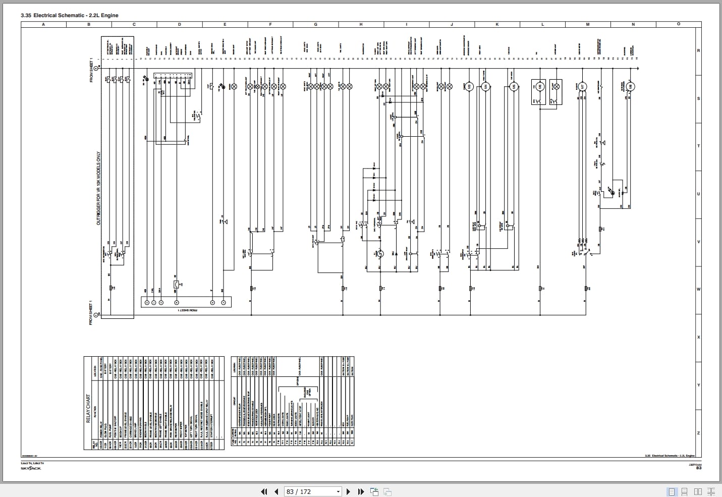
3.35 Electrical Schematic – 2.2L Engine
3.36 Electrical Schematic, Premium Joystick – 2.2L Engine
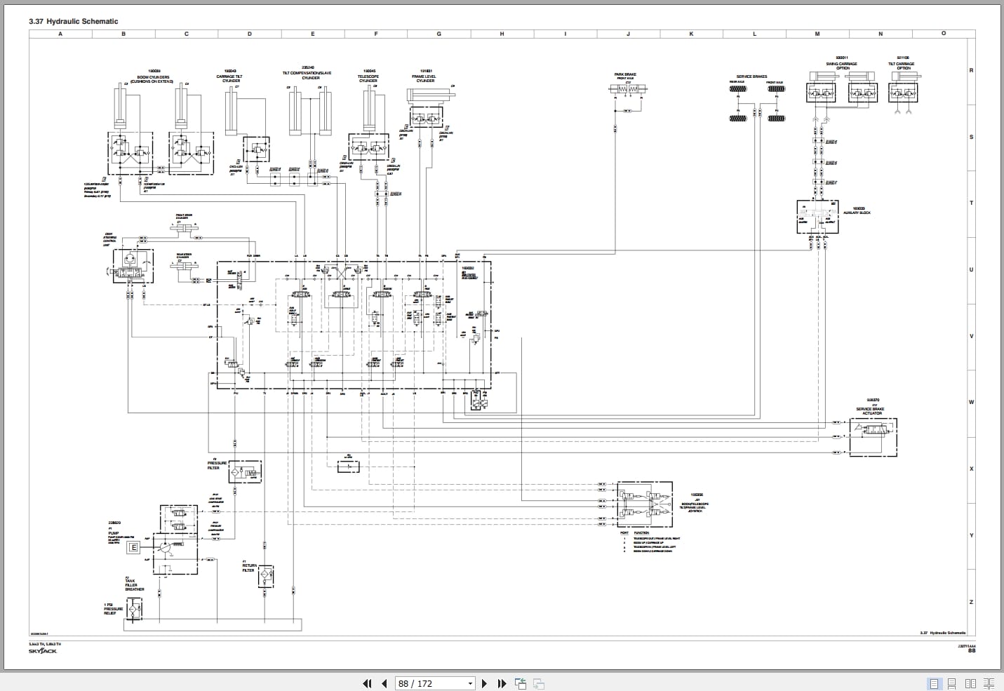
3.37 Hydraulic Schematic
3.38 Hydraulic Schematic – Premium Joystick
Section 4 – Troubleshooting Information
4.1 Introduction
4.2 Electrical System
4.3 Hydraulic System
Section 5 – Procedures
5.1 General
5.2 10 Hour or Daily Routine Maintenance
5.3 50 Hour or Weekly Routine Maintenance
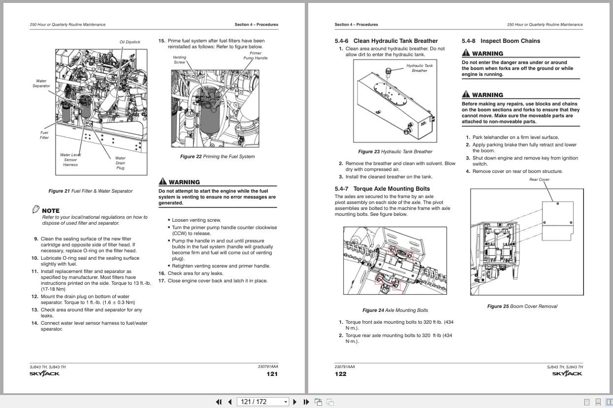
5.4 250 Hour or Quarterly Routine Maintenance
5.5 1000 Hour or Annual Routine Maintenance
5.6 Non-Routine Maintenance
5.7 Electronic Tilt Switch Setup Procedure
5.8 Park Brake Release
5.9 Bearing Installation
Related Products
-
Skyjack Lift Aerial Working Platform AWP All Models 2020 Documentation PDF DVD
Original price was: 200.110Current price is: 110. USDSkyjack Lift Aerial Working Platform AWP All Models 2020 Documentation PDF DVDSize: 6.39 GBFormat: PDFLanguage: EnglishBrand: Skyjack LiftAmount of DVD: 1 DVDWindow: All Window 32 & 64 bit, Mac OSType of Vehicle: Aerial working platform (AWP)Type of Document: Operating – Parts – Service Manuals PDFHot-45%
REALEASE :
30.05.2020
REALEASE :
30.05.2020
-
Skyjack Vertical Mast Lifts SJ12E SJ16E SJ20E Operating Manual 243762ABA 2022
10 USDSize: 5.67 MBFormat: PDFLanguage: EnglishBrand: SkyjackType of Machine: Vertical Mast LiftsType of Manual: Operating ManualModel: Skyjack SJ12E, SJ16E, SJ20E Vertical Mast LiftsSerial Number: A601001639 & abovePart Number: 243762ABAPublication Date: 2022Number of Pages: 92 Pages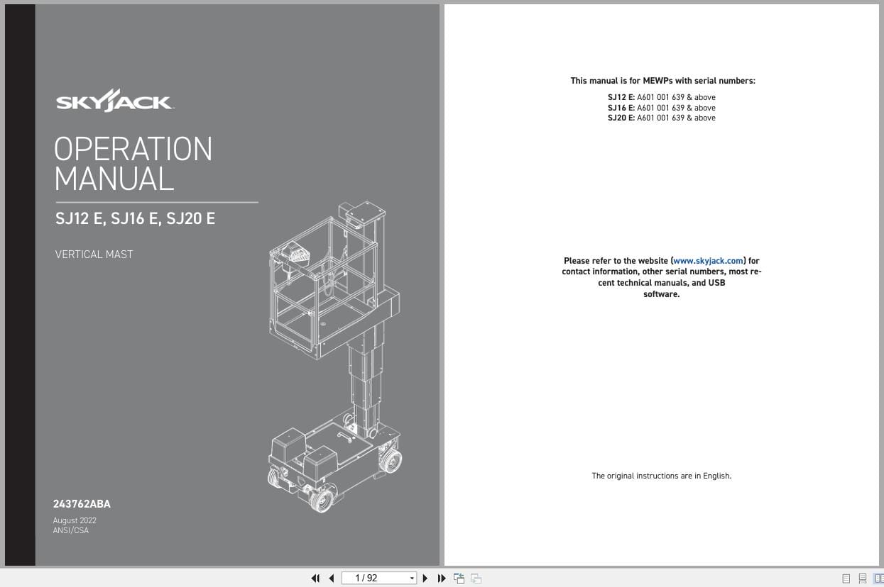
REALEASE :
REALEASE :
-
Skyjack NA 4.93GB PDF Operating Parts Service Manuals
Original price was: 200.140Current price is: 140. USDThis is a service information package, you will need to use this to repair a vehicleHot-30%
REALEASE :
REALEASE :
-
Skyjack Vertical Mast Lifts SJ12E SJ16E SJ20E Service Manual 241914ADA 2023
20 USDSize: 10.70 MBFormat: PDFLanguage: EnglishBrand: SkyjackType of Machine: Vertical Mast LiftsType of Manual: Service Manual, Electrical SchematicModel: Skyjack SJ12E, SJ16E, SJ20E Vertical Mast LiftsSerial Number: A601000906 – A601999999Part Number: 241914ADAPublication Date: 2023Number of Pages: 154 Pages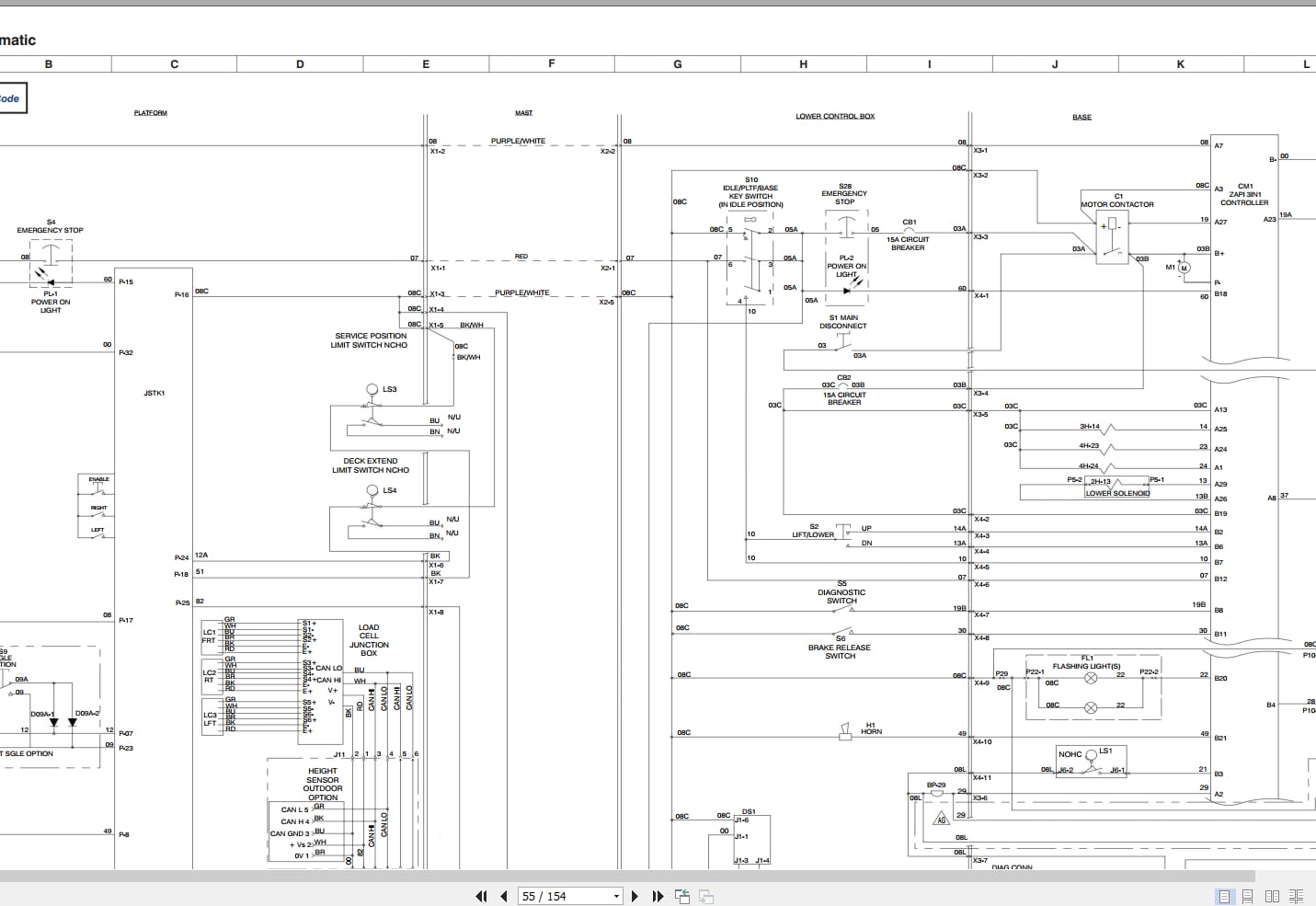
REALEASE :
REALEASE :
-
Skyjack Vertical Mast Lifts SJ12E SJ16E SJ20E Parts Manual 241913ADA 2023
15 USDSize: 7.44 MBFormat: PDFLanguage: EnglishBrand: SkyjackType of Machine: Vertical Mast LiftsType of Manual: Parts ManualModel: Skyjack SJ12E, SJ16E, SJ20E Vertical Mast LiftsSerial Number: A601000906 – A601999999Part Number: 241913ADAPublication Date: 2023Number of Pages: 138 Pages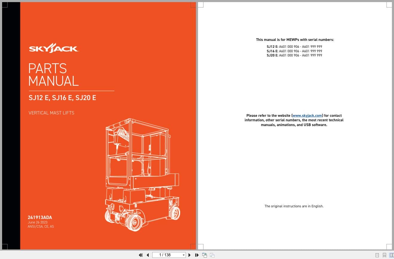
REALEASE :
REALEASE :
-
Skyjack Vertical Mast Lifts SJ20 Operating Manual 236504AFA 2022
10 USDSize: 5.17 MBFormat: PDFLanguage: EnglishBrand: SkyjackType of Machine: Vertical Mast LiftsType of Manual: Operating ManualModel: Skyjack SJ20 Vertical Mast LiftsSerial Number: A601000001 – A601000905Part Number: 236504AFAPublication Date: 2022Number of Pages: 94 Pages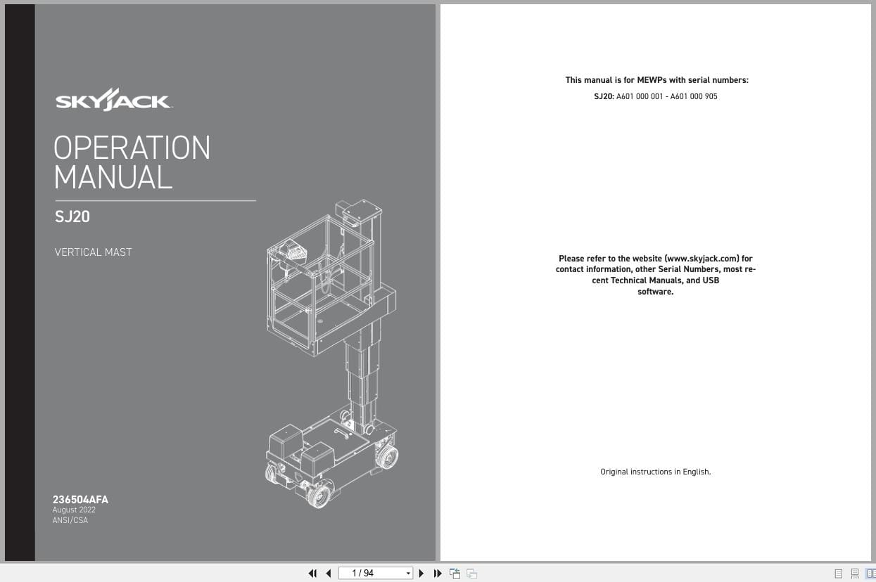
REALEASE :
REALEASE :
-
Skyjack Vertical Mast Lifts SJ20 Parts Manual 238885ACA 2023
15 USDSize: 6.43 MBFormat: PDFLanguage: EnglishBrand: SkyjackType of Machine: Vertical Mast LiftsType of Manual: Parts ManualModel: Skyjack SJ20 Vertical Mast LiftsSerial Number: A601000001 to A601000905Part Number: 238885ACAPublication Date: 2023Number of Pages: 116 Pages
REALEASE :
REALEASE :
-
Skyjack Vertical Mast Lifts SJ20 Service Manual 238886ADA 2023
20 USDSize: 9.74 MBFormat: PDFLanguage: EnglishBrand: SkyjackType of Machine: Vertical Mast LiftsType of Manual: Service Manual, Electrical SchematicModel: Skyjack SJ20 Vertical Mast LiftsSerial Number: A601000001 to A601000905Part Number: 238886ADAPublication Date: 2023Number of Pages: 158 Pages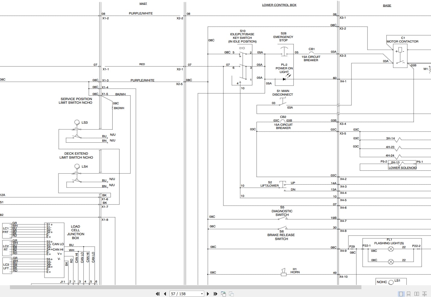
REALEASE :
REALEASE :