
0 ITEMSVIEW CART

✓
Expert Support
✓
Full Speed
✓
100% Working
Skyjack Telescopic Booms SJ61T SJ66T Service Manual 207564AL 2023
Size: 72.66 MB
Format: PDF
Language: English
Brand: Skyjack
Type of Machine: Telescopic Booms
Type of Manual: Service Manual, Electrical Schematic, Hydraulic Schematic
Model: Skyjack SJ61T, SJ66T Telescopic Booms
Serial Number: 97001833 to 97099999
Part Number: 207564AL
Publication Date: 2023
Number of Pages: 310 Pages
20 USD
- Description
Description
Contents:
Section 1 – Scheduled Maintenance
1.1 Read and Heed
1.2 Maintenance and Service
1.3 Scheduled Maintenance
1.4 Owner’s Annual Inspection Record
1.5 Pre-Delivery/Maintenance Inspection Checklist
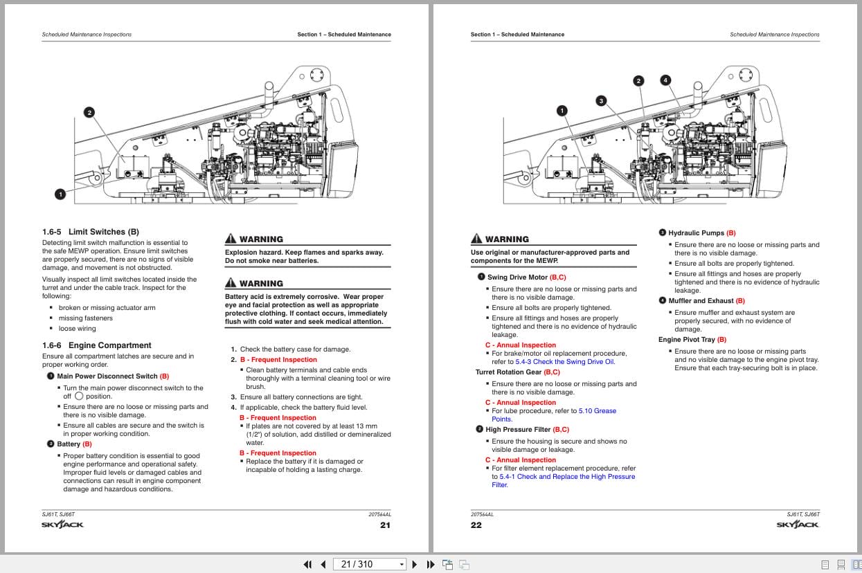
1.6 Scheduled Maintenance Inspections
1.7 Function Tests
Section 2 – Maintenance Tables and Diagrams
2.1 Standard Hose Numbering System
2.2 MEWP Torque Specifications
2.3 Axle Torque Specifications
2.4 Torque Specifications for Fasteners (US)
2.5 Torque Specifications for Fasteners (Metric)
2.6 Torque Specifications for Hydraulic Couplings & Hoses
2.7 Axle Maintenance Intervals
2.8 Tire Specifications
2.9 Floor Loading Pressure
2.10 Hydraulic Specifications & Gear Oil
2.11 Specifications and Features – Dimensional Data
2.12 Specifications and Features – Performance & Speeds
2.13 Engine Specifications
2.14 Dimension and Reach Diagram – SJ61T
2.15 Dimension and Reach Diagram – SJ66T
2.16 Axle Oscillation Diagrams
Section 3 – System Component Identification and Schematics
3.1 Electrical Symbol Chart
3.2 Hydraulic Symbol Chart
3.3 Wire Number and Color Code
3.4 Wire Numbers and Color Codes – Additional
3.5 Hydraulic Parts List
3.6 Electrical Parts List
3.7 Rotary Manifold Port Identification
3.8 Brake Manifold Port Identification
3.9 System and Drive Pumps and Port Identifications
3.10 System Pump and Port Identifications
3.11 Drive Pump and Port Identifications
3.12 Drive Motors and Port Identifications
3.13 Platform Rotate Valve and Port Identification – SJ61T
3.14 Jib & Platform Rotate Valve and Port Identification – SJ66T
3.15 Main Manifold Port Identification
3.16 Main Manifold Electrical Component Identification
3.17 Main Manifold Hydraulic Component Identification
3.18 Generator Control Valves and Port Indentifcations
3.19 Main Harness Wiring Diagram
3.20 ECU Engine Wiring Diagram – Deutz
3.21 Glow Plug and EGR Harnesses – Deutz
3.22 Engine Interface Harness – Deutz TD2.9L
3.23 Harnesses
3.24 Platform Control Cables
3.25 Limit Switch Connections
3.26 Load Sensing Cable Connection – CE
3.27 Generator and Oil Cooler Harness Connections
3.28 Generator Wire Kit Connections
3.29 Generator Connection – 12 kW
3.30 SGE Schematic
3.31 SGE Platform Control Box Wiring
3.32 Differential Lock Harness
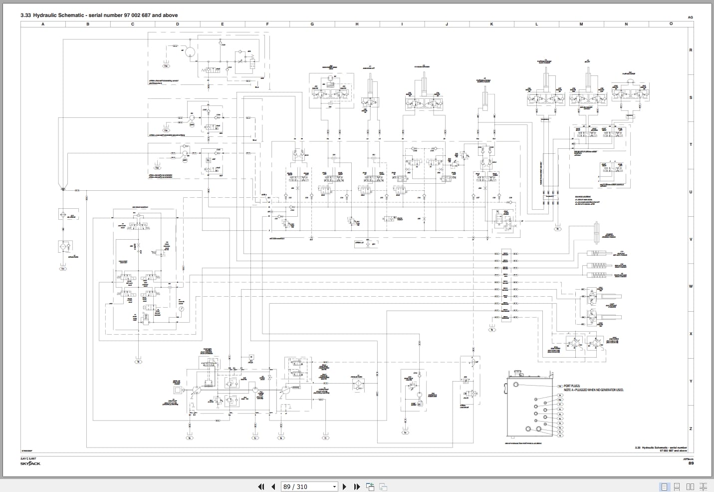
3.33 Hydraulic Schematic – serial number 97 002 687 and above
3.34 Hydraulic Schematic – serial number 97 002 686 and below
3.35 Platform Controls Wiring – SJ61T ANSI/CSA – Deutz & Perkins
3.36 Platform Controls Wiring – SJ61T ANSI/CSA – Kubota
3.37 Platform Controls Wiring – SJ66T ANSI/CSA – Deutz & Perkins
3.38 Platform Controls Wiring – SJ66T ANSI/CSA – Kubota
3.39 Platform Controls Wiring – SJ66T CE – Deutz TCD2.2
3.40 Platform Controls Wiring – SJ66T CE – Deutz TD2.9L & D2011
3.41 Platform Controls Wiring – SJ66T AS – Deutz
3.42 Base Controls Wiring – SJ61T ANSI/CSA – Deutz TD2.9L – S/N 97 003 631 & above
3.43 Base Controls Wiring – SJ61T ANSI/CSA – Deutz TD2.9L – S/N 97 003 630 & below
3.44 Base Controls Wiring – SJ61T ANSI/CSA – Deutz TD2.9L with Positive Air Shut-Off Option – S/N 97 003 631 & above
3.45 Base Controls Wiring – SJ61T ANSI/CSA – Deutz TD2.9L with Positive Air Shut-Off Option – S/N 97 003 630 & below
3.46 Base Controls Wiring – SJ61T ANSI/CSA – Deutz D2011 – S/N 97 003 631 & above
3.47 Base Controls Wiring – SJ61T ANSI/CSA – Deutz D2011 – S/N 97 003 630 & below
3.48 Base Controls Wiring – SJ61T ANSI/CSA – Deutz D2011with Positive Air Shut-Off Option – S/N 97 003 631 & above
3.49 Base Controls Wiring – SJ61T ANSI/CSA – Deutz D2011with Positive Air Shut-Off Option – S/N 97 003 630 & below
3.50 Base Controls Wiring – SJ61T ANSI/CSA – Perkins – S/N 97 003 631 & above
3.51 Base Controls Wiring – SJ61T ANSI/CSA – Perkins – S/N 97 003 630 & below
3.52 Base Controls Wiring – SJ61T ANSI/CSA – Kubota – S/N 97 003 631 & above
3.53 Base Controls Wiring – SJ61T ANSI/CSA – Kubota – S/N 97 003 630 & below
3.54 Base Controls Wiring – SJ66T ANSI/CSA – Deutz TD2.9L – S/N 97 003 631 & above
3.55 Base Controls Wiring – SJ66T ANSI/CSA – Deutz TD2.9L – S/N 97 003 630 & below
3.56 Base Controls Wiring – SJ66T ANSI/CSA – Deutz TD2.9L with Positive Air Shut-Off Option – S/N 97 003 631 & above
3.57 Base Controls Wiring – SJ66T ANSI/CSA – Deutz TD2.9L with Positive Air Shut-Off Option – S/N 97 003 630 & below
3.58 Base Controls Wiring – SJ66T ANSI/CSA – Deutz D2011 – S/N 97 003 631 & above
3.59 Base Controls Wiring – SJ66T ANSI/CSA – Deutz D2011 – S/N 97 003 630 & below
3.60 Base Controls Wiring – SJ66T ANSI/CSA – Deutz D2011 with Positive Air Shut-Off Option – S/N 97 003 631 & above
3.61 Base Controls Wiring – SJ66T ANSI/CSA – Deutz D2011 with Positive Air Shut-Off Option – S/N 97 003 630 & below
3.62 Base Controls Wiring – SJ66T ANSI/CSA – Perkins 2.2TA – S/N 97 003 631 & above
3.63 Base Controls Wiring – SJ66T ANSI/CSA – Perkins 2.2TA – S/N 97 003 630 & below
3.64 Base Controls Wiring – SJ66T ANSI/CSA – Kubota – S/N 97 003 631 & above
3.65 Base Controls Wiring – SJ66T ANSI/CSA – Kubota – S/N 97 003 630 & below
3.66 Base Controls Wiring – SJ66T CE – Deutz TCD2.2
3.67 Base Controls Wiring – SJ66T CE Deutz – TD2.9L
3.68 Base Controls Wiring – SJ66T CE – Deutz D2011 – S/N 97 003 631 & above
3.69 Base Controls Wiring – SJ66T CE – Deutz D2011 – S/N 97 003 630 & below
3.70 Base Controls Wiring – SJ66T AS – Deutz D2011 – S/N 97 003 631 & above
3.71 Base Controls Wiring – SJ66T AS – Deutz D2011 – S/N 97 003 630 & below
3.72 Electrical Schematic – ANSI/CSA – Deutz TD2.9L – S/N 97 003 631 and above
3.73 Electrical Schematic – ANSI/CSA – Deutz TD2.9L (S/N 97003799 and below)
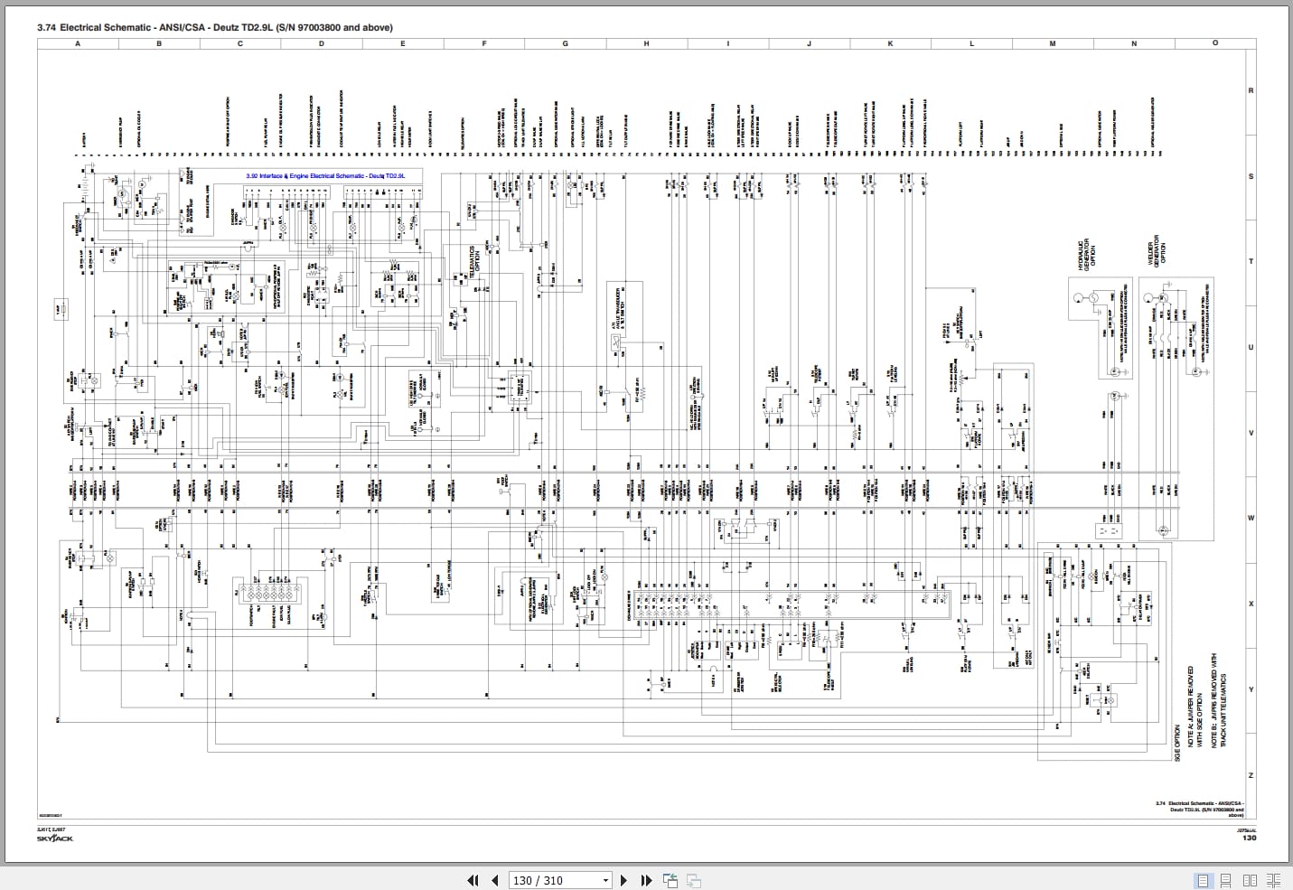
3.74 Electrical Schematic – ANSI/CSA – Deutz TD2.9L (S/N 97003800 and above)
3.75 Electrical Schematic – ANSI/CSA – Deutz D2011 – S/N 97 003 631 and above
3.76 Electrical Schematic – ANSI/CSA – Deutz D2011 (S/N 97003799 and below)
3.77 Electrical Schematic – ANSI/CSA – Deutz D2011 (S/N 97003800 and above)
3.78 Electrical Schematic – ANSI/CSA – Perkins 2.2TA (S/N 97003799 and below)
3.79 Electrical Schematic – ANSI/CSA – Perkins 2.2TA (S/N 97003800 and above)
3.80 Electrical Schematic – ANSI/CSA – Kubota – S/N 97 003 631 & above
3.81 Electrical Schematic – ANSI/CSA – Kubota (S/N 97003799 and below)
3.82 Electrical Schematic – ANSI/CSA – Kubota (S/N 97003800 and above)
3.83 Electrical Schematic – CE – Deutz TCD2.2
3.84 Electrical Schematic – CE – Deutz TD2.9L (S/N 97003799 and below)
3.85 Electrical Schematic – CE – Deutz TD2.9L (S/N 97003800 and above)
3.86 Electrical Schematic – CE – Deutz D2011 (S/N 97003799 and below)
3.87 Electrical Schematic – CE – Deutz D2011 (S/N 97003800 and above)
3.88 Electrical Schematic – AS – Deutz D2011 (S/N 97003799 and below)
3.89 Electrical Schematic – AS – Deutz D2011 (S/N 97003800 and above)
3.90 Interface & Engine Electrical Schematic – Deutz TCD2.2
3.91 Engine OEM Harness Schematic – Deutz TCD2.2
3.92 Interface & Engine Electrical Schematic – Deutz TD2.9L
3.93 Engine Interface Harness Schematic – Perkins
3.94 Engine OEM Harness Schematic – Perkins
3.95 Engine Component Harness Schematic – Perkins
3.96 Interface & Engine Electrical Schematic – Kubota
Section 4 – Troubleshooting Information
4.1 Introduction
4.2 Electrical System
4.3 Hydraulic System
4.4 Load Sensing System – CE
Section 5 – Procedures
5.1 General
5.2 Platform
5.3 Boom
5.4 Turret
5.5 Deutz Diesel Engines
5.6 Kubota WG2503 Dual Fuel Engine
5.7 Hydraulic Tank
5.8 Manifold and Hydraulic Pumps
5.9 Axles
5.10 Grease Points
5.11 Options
Related Products
-
Skyjack Vertical Mast Lifts SJ12E SJ16E SJ20E Parts Manual 241913ADA 2023
15 USDSize: 7.44 MBFormat: PDFLanguage: EnglishBrand: SkyjackType of Machine: Vertical Mast LiftsType of Manual: Parts ManualModel: Skyjack SJ12E, SJ16E, SJ20E Vertical Mast LiftsSerial Number: A601000906 – A601999999Part Number: 241913ADAPublication Date: 2023Number of Pages: 138 Pages
REALEASE :
REALEASE :
-
Skyjack Vertical Mast Lifts SJ12E SJ16E SJ20E Service Manual 241914ADA 2023
20 USDSize: 10.70 MBFormat: PDFLanguage: EnglishBrand: SkyjackType of Machine: Vertical Mast LiftsType of Manual: Service Manual, Electrical SchematicModel: Skyjack SJ12E, SJ16E, SJ20E Vertical Mast LiftsSerial Number: A601000906 – A601999999Part Number: 241914ADAPublication Date: 2023Number of Pages: 154 Pages
REALEASE :
REALEASE :
-
Skyjack Vertical Mast Lifts SJ20 Service Manual 238886ADA 2023
20 USDSize: 9.74 MBFormat: PDFLanguage: EnglishBrand: SkyjackType of Machine: Vertical Mast LiftsType of Manual: Service Manual, Electrical SchematicModel: Skyjack SJ20 Vertical Mast LiftsSerial Number: A601000001 to A601000905Part Number: 238886ADAPublication Date: 2023Number of Pages: 158 Pages
REALEASE :
REALEASE :
-
Skyjack Vertical Mast Lifts SJ20 Operating Manual 236504AFA 2022
10 USDSize: 5.17 MBFormat: PDFLanguage: EnglishBrand: SkyjackType of Machine: Vertical Mast LiftsType of Manual: Operating ManualModel: Skyjack SJ20 Vertical Mast LiftsSerial Number: A601000001 – A601000905Part Number: 236504AFAPublication Date: 2022Number of Pages: 94 Pages
REALEASE :
REALEASE :
-
Skyjack Vertical Mast Lifts SJ12E SJ16E SJ20E Operating Manual 243762ABA 2022
10 USDSize: 5.67 MBFormat: PDFLanguage: EnglishBrand: SkyjackType of Machine: Vertical Mast LiftsType of Manual: Operating ManualModel: Skyjack SJ12E, SJ16E, SJ20E Vertical Mast LiftsSerial Number: A601001639 & abovePart Number: 243762ABAPublication Date: 2022Number of Pages: 92 Pages
REALEASE :
REALEASE :
-
Skyjack Vertical Mast Lifts SJ20 Parts Manual 238885ACA 2023
15 USDSize: 6.43 MBFormat: PDFLanguage: EnglishBrand: SkyjackType of Machine: Vertical Mast LiftsType of Manual: Parts ManualModel: Skyjack SJ20 Vertical Mast LiftsSerial Number: A601000001 to A601000905Part Number: 238885ACAPublication Date: 2023Number of Pages: 116 Pages
REALEASE :
REALEASE :
-
Skyjack Lift Aerial Working Platform AWP All Models 2020 Documentation PDF DVD
Original price was: 200.110Current price is: 110. USDSkyjack Lift Aerial Working Platform AWP All Models 2020 Documentation PDF DVDSize: 6.39 GBFormat: PDFLanguage: EnglishBrand: Skyjack LiftAmount of DVD: 1 DVDWindow: All Window 32 & 64 bit, Mac OSType of Vehicle: Aerial working platform (AWP)Type of Document: Operating – Parts – Service Manuals PDFHot-45%
REALEASE :
30.05.2020
REALEASE :
30.05.2020
-
Skyjack NA 4.93GB PDF Operating Parts Service Manuals
Original price was: 200.140Current price is: 140. USDThis is a service information package, you will need to use this to repair a vehicleHot-30%
REALEASE :
REALEASE :