
7 ITEMSVIEW CART


Total: 870.00
Expert Support
Full Speed
100% Working
20 USD
Contents:
Introduction
Warranty
About Inspection and Maintenance
In Event of Failure
Service Life of Machine
Taking Machine Out of Country (Including Mobile
Communication Terminals, Wireless LAN Devices,
Radio Control Device)
For Safety
Contents
Name of Each Part
Contents with Illustrations
Traveling System
Crane Control System
Other Controls
Safety Precaution
Precautions before Starting Engine
Precautions for Traveling on Roads
Precautions during Operation
Precautions for Using Setup Radio Controller
Warning Labels
Label Location and Content of Warnings
TRAVELING
Before Traveling
Checking Traveling Configuration
Status of Traveling Controls
Inspection before Traveling
Entering Cab
Opening/Closing Door
Opening/Closing Window
Adjusting Seat
Adjusting Steering Wheel
Adjusting Mirrors
Fastening/Unfastening Seat Belt
Stowing Control Lever Stand
Sunshade
How to Read Instrument Panel and MFD
Meters and Gauges
Urea SCR System Indicator
Warning Sign
Error Codes Shown on MFD
TADANO View System
Camera Positions
Displaying Camera Images
Wide Sight View
Human Alert System
Front Left Camera
Starting and Stopping Engine
Starter Switch
How to Start Engine
How to Stop Engine
Exhaust Gas Purifying System
DEF/AdBlue (Urea Solution)
Cleaning of Urea SCR System
Transmission Operation
Positions and Functions of Gearshift Switch.
Gearshift Switch Operation
Setting Power Mode
Brake Operation
Foot Brake Operation
Parking Brake Operation
Engine Retarder Operation
Retarder Operation
Auxiliary Operating Brake (AUX)
Steering Operation
Selecting Steering Mode
Selecting Drive Mode
Selecting Drive Mode
Differential Lock Operation
Switching Differential Lock
Suspension Operation
Suspension Free Operation
Vehicle Height Up/Down Operation
Fully Retracting Suspension
Lighting Switch and Other Switches
Light Switch
Turn Signal Lever
Hazard Lamp Switch
Horn Switch
Wiper
Accessories in Cab
Fuel Consumption Monitor
Alarm Buzzer Muting Function
Dimming of MFD Screen
Preset Menu
Folding/Unfolding Rearview Mirrors
Mirror Heater
Air Conditioner
Tachograph
AM/FM Radio
How to Use Other Accessories
Outside Cab Accessories
Steps (Stowing Type)
Operation in Cold Season
Winterization/Inspection
OPERATION
Terminology
Anchor Point for Fall-arrest System
Location of Anchor Points
Before Crane Operation
Pre-operational Inspection
Preparing for Crane Operation
How to Read Performance Data Plates
Working Range Chart
Rated Lifting Capacity Table
Working Area Chart
AML (Automatic Moment Limiter)
How to Read Indication
Selecting Display
Crane Status Indicator
Lift Status Registration and AML Function
Check
Alarm and Recovery Operation
Other Functions
When Error Occurs in AML System
Other Safety Devices
Anti-two-block Device
AML External Warning lamp
Stop Switch
Anemometer (Option)
PTO Operation
PTO ON Operation
PTO OFF Operation
Setup Radio Controller
Mode Select
Safety Function
Preparation for Radio Control Operation
Basic Operation
Switching from Radio Control Operation to Opera
inside Cab
Other Functions
Receiver
Outrigger Operation
Control System
Crane Operation Mode
Outrigger Operation Mode
Extension Width of Outriggers and Appearance o
Marks on Side of Outrigger Beams
Cautions for Setting Up Outriggers
Setting Up Pads
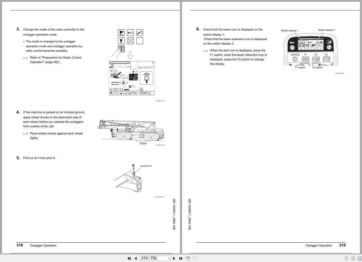
Outrigger Extending Operation from Outrigger
Control Panel/Box
Outrigger Extending Operation Using Radio
Control
Horizontal Set-up
Outrigger Stowing Operation from Outrigger Con
Panel/Box
Outrigger Stowing Operation Using Radio
Control
Stowing Pads
Adjusting Control Lever Stand and Control
Lever
Adjusting Control Lever Stand
Adjusting Control Lever
Winch Operation
Hoisting Up/Down
High-speed Hoist Down
Drum Indicator
Boom Telescoping Operation
How to Read Indication
Outline of Telescoping Modes
Type of Telescoping Mode
Normal Telescoping Operation
Telescoping Operation with Load Lifted
Maintenance Telescoping Operation
Boom Telescoping Speed Changeover
Operation
Boom Elevating Operation
Boom Elevating Operation
Elevation Slow Stop/Cancel Operation
Slewing Operation
Slewing Operation
Slewing Free Switch
Traveling on Work Site
Traveling Configuration in Work Site
On-rubber Operation
On-rubber (Stationary) Operation
On-rubber (Creep) Operation
Outrigger Operation
Control System
Crane Operation Mode
Outrigger Operation Mode
Extension Width of Outriggers and Appearance o
Marks on Side of Outrigger Beams
Cautions for Setting Up Outriggers
Setting Up Pads
Outrigger Extending Operation from Outrigger
Control Panel/Box
Outrigger Extending Operation Using Radio
Control
Horizontal Set-up
Outrigger Stowing Operation from Outrigger Con
Panel/Box
Outrigger Stowing Operation Using Radio
Control
Stowing Pads
Adjusting Control Lever Stand and Control
Lever
Adjusting Control Lever Stand
Adjusting Control Lever
Winch Operation
Hoisting Up/Down
High-speed Hoist Down
Drum Indicator
Boom Telescoping Operation
How to Read Indication
Outline of Telescoping Modes
Type of Telescoping Mode
Normal Telescoping Operation
Telescoping Operation with Load Lifted
Maintenance Telescoping Operation
Boom Telescoping Speed Changeover
Operation
Boom Elevating Operation
Boom Elevating Operation
Elevation Slow Stop/Cancel Operation
Slewing Operation
Slewing Operation
Slewing Free Switch
Traveling on Work Site
Traveling Configuration in Work Site
On-rubber Operation
On-rubber (Stationary) Operation
On-rubber (Creep) Operation
Taking Out and Stowing Hook Block
Taking Out Hook Block
Stowing Hook Block
Reeving Wire Rope
Standard Number of Parts of Line
Reeving Procedure
Heavy Load Lifting Device
Check Before Using Heavy Load Lifting Device.
Single Top
Check Before Single Top Lift
Full Automatic Jib
Jib Lift
Jib Set Mode
Outline of Jib Mounting
Mounting Jib
Changing Jib Length
Changing Jib Offset Angle
Outline of Jib Stowing
Stowing Jib
Mounting and Dismounting Counterweight.
Rigging Point of Counterweight
Assembling Counterweight
Mounting Counterweight
Dismounting Counterweight
Transportation Configuration
Disassembling Counterweight
Storing Counterweight
Counterweight Jack Interlock
Accessories in Cab
Fuel Consumption Monitor
MFD Operation Switch
Flood Lamp Button
Alarm Buzzer Muting Function
Dimming MFD Screen
Folding/Unfolding Rearview Mirrors
Mirror Heater
Roof Washer Switch
Roof Wiper Switch
Microphone Control Box
Table
Drink Holder
Searchlight (Option)
Outside Cab Accessories
Oil Cooler
Stepladder
INSPECTION AND MAINTENANCE
Precautions for Inspection and Maintenance.
Precautions for Inspection and Maintenance
Inspection and Maintenance
About Inspection and Maintenance
Under Severe Use (Severe Condition)
Conditions of Severe Use
Periodic Replacement Parts
Inspection and Maintenance Interval (Carrier)
Inspection and Maintenance Interval (Crane)
Inspection before Traveling
Irregularities Detected on Previous Day or
Operation
Inspection Around Carrier
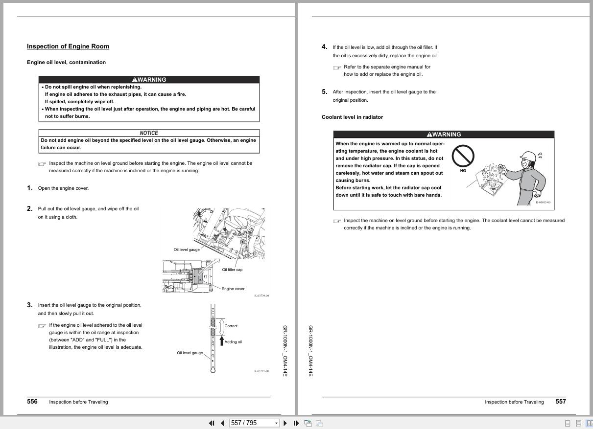
Inspection of Engine Room
Inspection at Driver’s Seat
Pre-operational Inspection
Hydraulic System
Control System
Outrigger System
Slewing System
Boom, Jib System
Lifting Device
Safety Devices
Inspection of Crane Structure
Boom Structure
Jib Structure
Slewing Frame
Outrigger Structure
Chassis Frame
Greasing
Greasing Chart
Greasing (Centralized Greasing Supply Unit)
Using Centralized Greasing Supply Unit
Greasing Period
Greasing Points
Adding Grease
Gear Oil
Winch Speed Reducer (Main/Auxiliary Winch)
Slewing Speed Reducer
1st Axle Hub and 2nd/3rd/4th Axle Planetary
Gear
2nd/3rd/4th Axle Carrier
Engine
Radiator
Air Cleaner for Air Compressor
DEF/AdBlue Tank
Retarder
Air Gap
Drum
Center Bearing
Engine Cooling System
Coolant Filter (Warm Water)
Transmission System
Transmission
Line Filter
Fuel System
Fuel Tank
Brake System
Brake Fluid Reservoir
Disc Brake Pad
Air Dryer
Air Tank
Tire, Wheel
Tires
Wheel Nut
Hydraulic System
Hydraulic Oil Tank
Return Filter
Line Filter (Steering/Slewing Pump Circuit).
Line Filter (P4 Circuit)
Telescoping System
Jib Telescoping Wire Rope
Slewing System
Slewing Bearing Mounting Bolt
Electrical System
Replace
Replacing Radio Controller Battery
Air Conditioner System
Condenser
Refrigerant Level
Refrigerant Piping Connection
Inside Air Filter, Outside Air Filter
V-belt
Periodic Replacement Parts
Wire Rope
Replacing Wire Rope
Handling Wire Ropes
EMERGENCY OPERATIONS
Action in Emergency
If Failure Occurs While Traveling on Road
If Stalled at Railroad Crossing
If Tires are Off Ground and Machine cannot
Move
If Transmission cannot be Operated
When Fuel Runs Out
When Overheating Occurs
When Towed
If Boom Telescoping Is Not Possible
Monitor Screen During Emergency Telescoping
Operation
Troubleshooting (A)
Troubleshooting (B)
Troubleshooting (C)
If Error Occurs in AML System
If Crane is not Operable
If Crane Does Not Stop Even If Control Lever is
Returned to Neutral Position
When Outrigger Jack Stowing Operation Is Not
Possible
When Steps Cannot Be Operated
When Counterweight Lifting Cylinders Extend
Spontaneously

REALEASE :
07.07.2022
REALEASE :
07.07.2022

REALEASE :
REALEASE :
REALEASE :

REALEASE :
07.07.2022
REALEASE :
07.07.2022

REALEASE :
30.06.2022
REALEASE :
30.06.2022

REALEASE :
13.07.2022
REALEASE :
13.07.2022

REALEASE :
REALEASE :

REALEASE :
REALEASE :
 Automotive - Heavy Equipment - Truck & Bus - Forklift - Crane