
0 ITEMSVIEW CART


✓
Expert Support
✓
Full Speed
✓
100% Working
Gradall Wheeled Excavator XL4300II Operators Parts Service Technical Manual
Size: 355.36 MB
Format: PDF
Language: English
Brand: Gradall
Type of Machine: Rough-terrain Wheeled Excavator
Type of Manual: Combined Service Manual, Electrical Schematic, Hydraulic Schematic, Illustrated Parts Manual, Operators Manual, Parts Manual, Service Manual, Technical Manual
Model: Gradall XL4300II Rough-terrain Wheeled Excavator
30 USD
- Description
Description
List of Files:
XL4300II Combined Service Manual 31200027 2004.pdf (912 Pages)
Contents:
31200027 XL4300 II Combined Service Manual
OPERATOR INSTRUCTION
31200014 XL4300 II Owner/Operator Manual
SCHEDULED MAINTENANCE
8090-9017 Critical Item Check Sheet
HYDRAULIC SYSTEM OPERATION
All Terrain Hydraulic System
8043-9002 Hydraulic Schematic
8043-9006 Start-Up Procedure
RA64-555 Rexroth Joystick
RA6479-S Rexroth Gear Pump
HYDRAULIC TEST & ADJUSTMENT
8043-9003 Final Test Report
MECHANICAL ADJUSTMENTS
1512-003 Parker Low Speed, High Torque Hydraulic Motors
75580 Ausco Brake Technical Page
29712 Boom Extension Installation Manual
ELECTRICAL
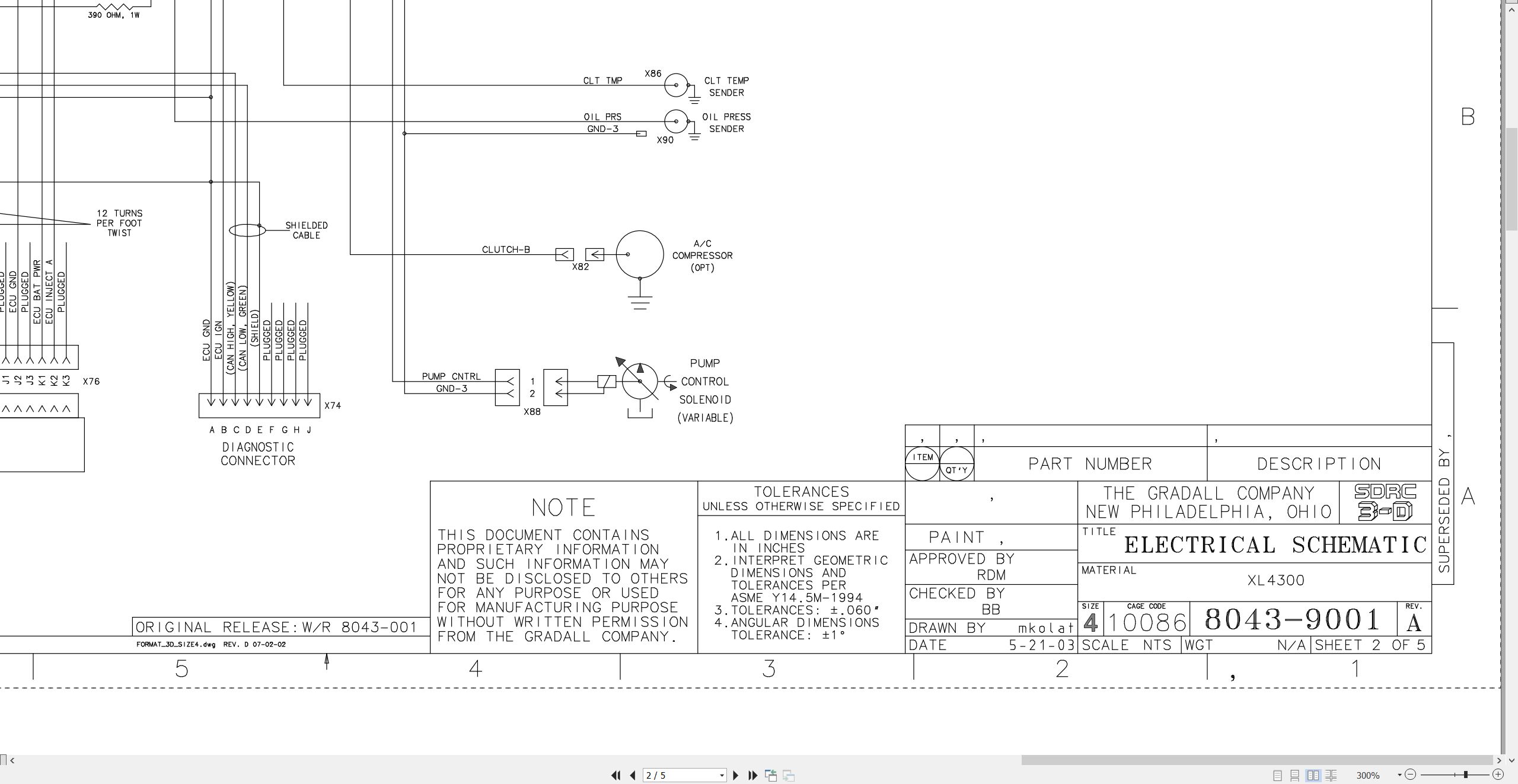
8043-9001 Electrical Schematic
1M-128 Delco Remy 28-MT Cranking Motor Service Manual
8046-3004 Upper Harness
8046-3113 Engine Harness
8046-3003 Cab Harness
8046-5002 Console Assembly
8046-3036 John Deere EMU
8046-3008 Upper VEC
8046-3012 RT Relay VEC
8046-3013 VEC PWR/GND Harness
DCMB Trojan Deep Cycle Battery Maintenance
BCI-II edition Trojan Battery Service Manual
125-189 Leece-Neville Alternators for Electronic Charging Systems
DRIVE AXLE
AP(L)-B 765/775 ZF-Planetary Axle w/Wet-Type Multiple-Disk Brakes Service
APL-B 765 ZF-Planetary Steering Axle Parts Manual
AP-B 765 ZF-Rear Axle Parts Manual
2 HL 100 ZF-Transfer Case Service Manual
2 HL 100 ZF-Hydrostatic Powershift Transmission Technical Manual
2 HL 100 ZF-Axle Transfer Case Parts Manual
WHEEL & RIM
0009 Rim & Wheel Safety Manual
MISCELLANEOUS
20013 Gradall Safety Manual
HE92-2 EMI Hydraulic Excavator Safety Manual
8060-9016 Hydraulic Fitting Torque Chart
XL4300II CE Operators Manual 31200154 2005.pdf (66 Pages)
XL4200II XL4300II Technical Manual 80414111 2011.pdf (576 Pages)
Contents:
80414111_XL4200II & XL4300II Technical Manual_5-11
ELECTRICAL
XL4200II Electrical System Manual
XL4300II Electrical System Manual
Engine Diagnostic Trouble Codes
XL4300II BB-3 Control Panel
HYDRAULIC
Hydraulic System Operation
XL4200II Hydraulic Pressure Setting Manual
XL4300II Hydraulic Pressure Setting Manual (Troubleshooting Guide)
XL4200II Final Test Report
XL4300II Final Test Report
MECHANICAL
XL4300II Maintenance Manual
XL4200II Maintenance Manual
Product Support Information – A/C System Reciever Dryers
Product Support Information – A/C Systems & Compressed Air
Product Support Information – A/C System Moisture Contamination
Product Support Information – Fan Clutch Maintenance
Product Support Information – Swing Transmission Lubricant Check & Refill Requirements
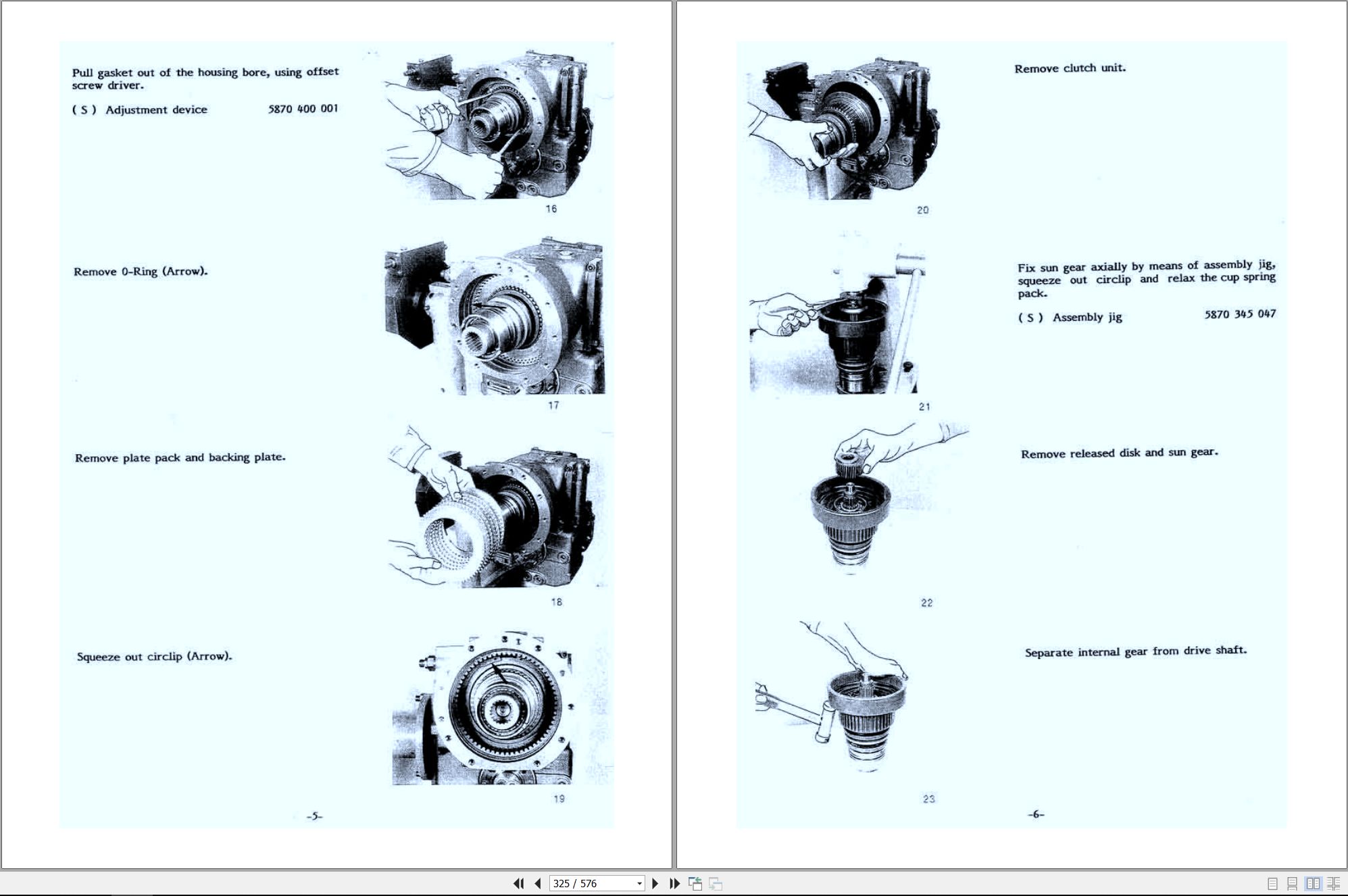
XL4300II Transmission Service Manual (ZF)
XL4300II Axle Service Manual (ZF)
SCHEMATICS
XL4200II Hydraulic Schematic (80419001)
XL4200II Electrical Schematic (80419011)
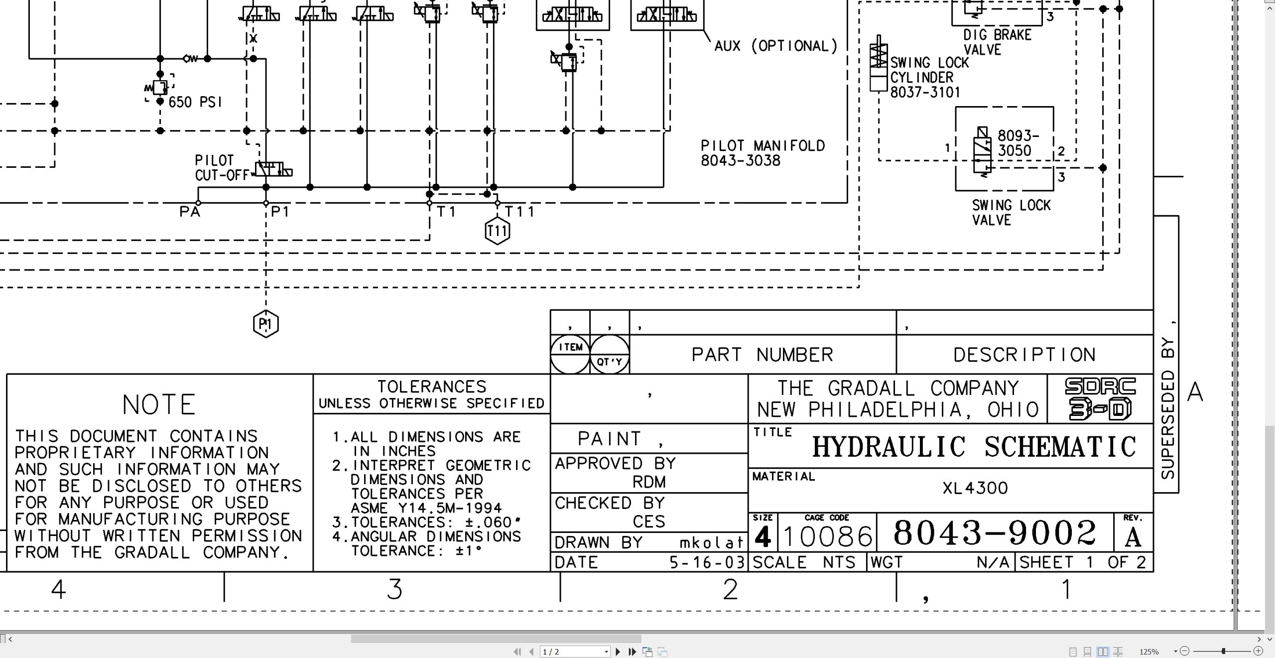
XL4300II Hydraulic Schematic (80439002)
XL4300II Electrical Schematic (80439001)
XL4300II Combined Service Manual 8043-4002 2006.pdf (926 Pages)
Contents:
8043-4002 XL4300 II Combined Service Manual
OPERATOR INSTRUCTION
20143 XL4300 II Owner/Operator Manual
SCHEDULED MAINTENANCE
8090-9017 Critical Item Checklist
HYDRAULIC SYSTEM OPERATION
All Terrain Hydraulic System
8043-9002 Hydraulic Schematic
8043-9006 Start-Up Procedure
RA64-555 Rexroth Joystick
RA6479-S Rexroth Gear Pump
HYDRAULIC TEST & ADJUSTMENT
8043-9003 Final Test Report
MECHANICAL ADJUSTMENTS
1512-003 Parker Low Speed, High Torque Hydraulic Motors
75580 Ausco Brake Technical Page
29712 Boom Extension Installation Manual
ELECTRICAL
8043-9001 Electrical Schematic
1M-128 Delco Remy 28-MT Cranking Motor Service Manual
8046-3004 Upper Harness
8046-3113 Engine Harness
8046-3003 Cab Harness
8046-5002 Console Assembly
8046-3036 John Deere EMU
8046-3008 Upper VEC
8046-3012 RT Relay VEC
8046-3013 VEC PWR/GND Harness
DCMB Trojan Deep Cycle Battery Maintenance
BCI-II edition Trojan Battery Service Manual
125-189 Leece-Neville Alternators for Electronic Charging Systems
DRIVE AXLE
AP(L)-B 765/775 ZF-Planetary Axle w/Wet-Type Multiple-Disk Brakes Service
APL-B 765 ZF-Planetary Steering Axle Parts Manual
AP-B 765 ZF-Rear Axle Parts Manual
2 HL 100 ZF-Transfer Case Service Manual
2 HL 100 ZF-Hydrostatic Powershift Transmission Technical Manual
2 HL 100 ZF-Axle Transfer Case Parts Manual
WHEEL & RIM
0009 Rim & Wheel Safety Manual
MISCELLANEOUS
20013 Gradall Safety Manual
HE92-2 EMI Safety Manual – 8060-3007.pdf
8060-9016 Hydraulic Fitting Torque Chart
XL4300II Operators Manual 8043-4003 2004.pdf (68 Pages)
XL4300II Illustrated Parts Manual 80434001 2025.pdf (456 Pages)
Contents:
Service Kits
Section 1 Frame & Attaching Parts
Figure 1-1 Frame & Attaching Parts
Figure 1-2 Rotating Platform, R.H. View
Figure 1-3 Rotating Platform, L.H. View
Figure 1-4 Swing Bearing, Cradle & Hoist Cylinder Mounting & Lube System
Figure 1-5 Frame & Plumbing
Figure 1-6 Engine Cover
Figure 1-7 Valve Cover
Figure 1-8 Front Cover
Section 2 Boom
Figure 2-1 Boom Cradle
Figure 2-2 Main Boom Assembly & Rollers
Figure 2-3 Telescope Boom Assembly
Figure 2-4 Roller Assemblies
Figure 2-5 Bucket Linkage
Section 3 Attachments
Figure 3-1 24†& 30†Excavating Buckets
Figure 3-2 36†& 42†Excavating Buckets
Figure 3-3 48†Excavating Bucket & 15†Trenching Bucket
Figure 3-4 18†& 28†Pavement Removal Bucket
Figure 3-5 40†Pavement Removal Bucket & 60†Ditching Bucket
Figure 3-6 28†Pavement Removal Bucket & 30†Ditching Bucket
Figure 3-7 60â€, 66†& 72†Ditching Bucket
Figure 3-8 72†& 108†Dredging Bucket
Figure 3-9 Guardrail Back Scraper & 66†Ditching Bucket
Figure 3-10 8’ Grading Blade & Single Tooth Ripper
Figure 3-11 4’ Boom Extension
Figure 3-12 6’ Boom Extension
Figure 3-13 8’ Boom Extension
Figure 3-14 12’ Boom Extension
Figure 3-15 Fixed Thumb Grapple
Figure 3-16 66†Ditching Bucket w/Bolt-on Cutting Edge
Figure 3-17 60†Ditching Bucket w/Bolt-on Cutting Edge
Section 4 Engine & Attaching Parts
Figure 4-1 Engine Assembly, L.H. View
Figure 4-2 Engine Assembly, R.H. View
Figure 4-3 Deere Engine
Figure 4-4 Air Cleaner & Installation
Figure 4-5 Air Cleaner
Figure 4-6 Exhaust System
Figure 4-7 Fuel Tank Assembly
Figure 4-8 Oil Cooler, Radiator & Hoses
Section 5 Drive Train
Figure 5-1 Transmission – Input Housing
Figure 5-2 Transmission – Input
Figure 5-3 Transmission – Housing
Figure 5-4 Transmission – Oil Pipe
Figure 5-5 Transmission – Coupling
Figure 5-6 Transmission – Disc Brake
Figure 5-7 Transmission – Planetary Drive
Figure 5-8 Transmission – Disconnection
Figure 5-9 Transmission – Spurred Gear Drive
Figure 5-10 Transmission – Shift Sensor
Figure 5-11 Transmission – Output
Figure 5-12 Steer Axle – Axle Housing
Figure 5-13 Steer Axle – Differential Spider, Cage & Nest
Figure 5-14 Steer Axle – Differential Carrier
Figure 5-15 Steer Axle – Wheel End
Figure 5-16 Steer Axle – Gearbox & Brake
Figure 5-17 Steer Axle – Steering Gear
Figure 5-18 Drive Axle – Axle Housing
Figure 5-19 Drive Axle – Differential
Figure 5-20 Drive Axle – Hub Carrier & Wheel End
Figure 5-21 Drive Axle – Gearbox & Brake
Section 6 Cab
Figure 6-1 Operators Cab
Figure 6-2 Operators Cab
Figure 6-3 Cab Door
Figure 6-4 Cab Interior Components
Figure 6-5 Cab Console
Figure 6-6 Cab Seat
Figure 6-7 Cab Heater & Installation
Figure 6-8 Wiper-Washer Installation Components
Figure 6-9 Pilot Cut-off Assembly
Section 7 Controls
Figure 7-1 Joystick
Figure 7-2 Steering Column, Foot Pedals & Installation
Section 8 Hydraulic Circuits
Figure 8-1 Oil Supply to Pumps
Figure 8-2 Hydraulic Pressure to Control Valves
Figure 8-3 Main Valve to Pilot Manifold Hydraulic Hosing
Figure 8-4 Dump Circuit
Figure 8-5 Hydraulic Hosing to Joysticks & Propel
Figure 8-6 Hoist Pilot
Figure 8-7 Boom Pilot
Figure 8-8 Tool Pilot
Figure 8-9 Swing & Swing Brake Pilot
Figure 8-10 Hoist Cylinder
Figure 8-11 Hoist Tubes Replacement Kit
Figure 8-12 Boom Cylinder
Figure 8-13 Tool Cylinder
Figure 8-14 Swing Motor
Figure 8-15 Swing Tubes Replacement Kit
Figure 8-16 Tilt Motor
Figure 8-17 Upper Propelling
Figure 8-18 Chassis Supply
Figure 8-19 Chassis Supply Pilot
Section 9 Hydraulic Components
Figure 9-1 Hoist Cylinder Assembly
Figure 9-2 Boom Cylinder Assembly
Figure 9-3 Tool Cylinder Assembly
Figure 9-4 Outrigger Cylinder Assembly
Figure 9-5 Oscillation Cylinder Assembly
Figure 9-6 Swing Lock Cylinder
Figure 9-7 Main Pump
Figure 9-8 Pilot Manifold Valve Tray
Figure 9-9 Pilot Manifold
Figure 9-10 Main Hydraulic Control Valve Assembly
Figure 9-11 Main Hydraulic Control Valve
Figure 9-12 Main Hydraulic Control Valve – Spools & End Caps
Figure 9-13 Main Hydraulic Control Valve – Swing Section
Figure 9-14 Main Hydraulic Control Valve – Seal Kits
Figure 9-15 Cold Start Valve
Figure 9-16 Reservoir Assembly
Figure 9-17 Swing Transmission Assembly
Figure 9-18 Swing Drive Assembly
Figure 9-19 Swing Motor
Figure 9-20 Swing Brake
Figure 9-21 Tilt Transmission Assembly
Figure 9-22 Tilt Drive Assembly
Figure 9-23 Tilt Brake Assembly
Figure 9-24 Tilt Motor
Figure 9-25 Drive Motor
Figure 9-26 Center Pin Assembly
Figure 9-27 Gear Pump
Figure 9-28 CE Gear Pump
Figure 9-29 Foot Operated Pedal Valve
Figure 9-30 Transmission Control Valve Assembly
Figure 9-31 Transmission Control Valve Installation
Figure 9-32 Outrigger Selector Valve Installation
Figure 9-33 Outrigger Selector Valve Assembly
Figure 9-34 Six Way Diverter Valve
Figure 9-35 Steering Control
Figure 9-36 Oscillation/Cylinder Anti-Drift Valve
Figure 9-37 Outrigger Valve Block
Figure 9-38 Swing Reduction Valve
Section 10 Electrical
Figure 10-1 Batteries & Miscellaneous Components
Figure 10-2 Cab Console
Section 11 Decals
Figure 11-1 Decals
Section 12 Options
Figure 12-1 Air Conditioner Installation Components
Figure 12-2 Air Conditioning Evaporator Kit
Figure 12-3 Auxiliary Hydraulic Valve Installation Components
Figure 12-4 Blade Cylinder Assembly
Figure 12-5 Blade Selector Valve Assembly
Figure 12-6 Bucket Hold Open Kit
Figure 12-7 Chassis Mounted Blade Installation Components
Figure 12-8 Cold Start Installation Components
Figure 12-9 Engine Block Heater Installation Components
Figure 12-10 Four Line Hose Trough Installation Components
Figure 12-11 Front Outrigger Installation Components
Figure 12-12 Front Outrigger Installation Components
Figure 12-13 Lexan Glass Installation Components
Figure 12-14 Light Installation Components
Figure 12-15 H.I.D. Light Installation Components
Figure 12-16 AM/FM Cassette Stereo Installation
Figure 12-17 Vandal Cover Installation Components
Figure 12-18 Auxiliary Hydraulic Valve Field Installation Components
Recommended Spare Parts
Part Number Index
XL4300II XL4310II Electrical Schematic 80439001.pdf (5 Pages)
XL4300II XL4310II Hydraulic Schematic 80439002.pdf (2 Pages)
Related Products
-
Gradall Wheeled Excavator XL3300V Operators Parts Service Manual
30 USDSize: 214.38 MBFormat: PDFLanguage: EnglishBrand: GradallType of Machine: Rough-terrain Wheeled ExcavatorType of Manual: Electrical Schematic, Hydraulic Schematic, Illustrated Parts Manual, Lubrication Chart, Operator Safety Manual, Parts Manual, Service SupplementModel: Gradall XL3300V Rough-terrain Wheeled Excavator
REALEASE :
REALEASE :
-
Gradall Wheeled Excavator XL3300III Operators Parts Service Manual
30 USDSize: 218.24 MBFormat: PDFLanguage: EnglishBrand: GradallType of Machine: Rough-terrain Wheeled ExcavatorType of Manual: Combined Service Manual, Electrical Schematic, Hydraulic Schematic, Illustrated Parts Manual, Lubrication Chart, Operator Manual, Safety Manual, Parts Manual, Service ManualModel: Gradall XL3300III Rough-terrain Wheeled Excavator
REALEASE :
REALEASE :
-
Gradall Wheeled Excavator XL4300 Operators Parts Service Manual
30 USDSize: 321.70 MBFormat: PDFLanguage: EnglishBrand: GradallType of Machine: Rough-terrain Wheeled ExcavatorType of Manual: Electrical Schematic, Hydraulic Schematic, Illustrated Parts Manual, Lubrication Chart, Operator Manual, Safety Manual, Parts Manual, Service Manual, Service SupplementModel: Gradall XL4300 Rough-terrain Wheeled Excavator
REALEASE :
REALEASE :
-
Gradall Wheeled Excavator XL5300 Operators Parts Service Manual
30 USDSize: 309.61 MBFormat: PDFLanguage: EnglishBrand: GradallType of Machine: Rough-terrain Wheeled ExcavatorType of Manual: Electrical Schematic, Hydraulic Schematic, Illustrated Parts Manual, Operator Manual, Safety Manual, Parts Manual, Service Manual, Service SupplementModel: Gradall XL5300 Rough-terrain Wheeled Excavator
REALEASE :
REALEASE :
-
Gradall Wheeled Excavator XL4300IICE Operators Service Manual 31200155 2006
30 USDSize: 130.81 MBFormat: PDFLanguage: EnglishBrand: GradallType of Machine: Rough-terrain Wheeled ExcavatorType of Manual: Combined Service Manual, Operators Manual, Hydraulic Schematic, Electrical SchematicModel: Gradall XL4300IICE 31200155, XL4300IICE 31200154 Rough-terrain Wheeled ExcavatorSerial Number: 0210017803Part Number: XL4300IICE 31200155, XL4300IICE 31200154Publication Date: 31200155 – 2006, 31200154 – 2005Number of Pages: 953 Pages
REALEASE :
REALEASE :
-
Gradall Wheeled Excavator XL4300V Operators Parts Service Manual
30 USDSize: 252.03 MBFormat: PDFLanguage: EnglishBrand: GradallType of Machine: Rough-terrain Wheeled ExcavatorType of Manual: Assembly Manual, Electrical Schematic, Hydraulic Schematic, Illustrated Parts Manual, Installation Instructions, Installation Parts Manual, Lubrication Chart, Maintenance Manual, Operator Manual, Safety Manual, Operators Instruction, Parts Manual, Service Supplement, User ManualModel: Gradall XL4300V Rough-terrain Wheeled Excavator
REALEASE :
REALEASE :
-
Gradall Wheeled Excavator XL5300III Operators Parts Service Manual
30 USDSize: 311.43 MBFormat: PDFLanguage: EnglishBrand: GradallType of Machine: Rough-terrain Wheeled ExcavatorType of Manual: Electrical Schematic, Hydraulic Schematic, Illustrated Parts Manual, Lubrication Chart, Operator Manual, Safety Manual, Parts Manual, Service Manual, Service SupplementModel: Gradall XL5300III Rough-terrain Wheeled Excavator
REALEASE :
REALEASE :
-
Gradall Wheeled Excavator XL5300V Operators Parts Service Manual
30 USDSize: 214.38 MBFormat: PDFLanguage: EnglishBrand: GradallType of Machine: Rough-terrain Wheeled ExcavatorType of Manual: Electrical Schematic, Hydraulic Schematic, Illustrated Parts Manual, Lubrication Chart, Operator Manual, Safety Manual, Parts Manual, Service SupplementModel: Gradall XL5300V Rough-terrain Wheeled Excavator
REALEASE :
REALEASE :