
0 ITEMSVIEW CART

✓
Expert Support
✓
Full Speed
✓
100% Working
Jacobsen Fairway Mower LF-3810 Parts Manual 2810361-C 2001
Size: 7.89 MB
Format: PDF
Language: English
Brand: Jacobsen
Type of Machine: Fairway Mower
Type of Manual: Parts Manual, Wiring Diagram, Hydraulic Diagram
Model: Jacobsen LF-3810 67827, LF-3810 67828 Fairway Mower
Engine:
67827 – Kubota V1505-E 2WD
67828 – Kubota V1505-E 4WD with ROPS
Part Number: 2810361-C
Publication Date: 2001
Number of Pages: 164 Pages
10 USD
- Description
Description
Contents:
Safety
1.1 Operating Safety
1.2 Important Safety Notes
SpecificationS
2.1 Product Identification
2.2 Engine
2.3 Tractor
2.4 Weights and Dimensions
2.5 Cutting Units
2.6 Accessories
2.7 Support Literature
Adjustments
3.1 General
3.2 Opening Hood and Operator’s Platform
3.3 Manual Lowering Valve
3.4 Engine Alternator Belt
3.5 Reel Drive Belt
3.6 Parking Brake
3.7 Parking Brake Switch
3.8 Steering Toe-In
3.9 Neutral Position Adjustment
3.10 Neutral start switch
3.11 4WD Reverse Switch
3.12 Mow Speed
3.13 Lift springs
3.14 Lift Switch
3.15 Reel To Bedknife
3.16 Reel to Bedknife Adjustment
3.17 Cutting Modes
3.18 Cutting Height – Fixed Mode
3.19 Cutting Height – Floating Mode
3.20 Deflector
3.21 Reel Limit Switches
3.22 Torque Specification
Maintenance
4.1 General
4.2 Engine
4.3 Engine Oil
4.4 Air filter
4.5 Fuel
4.6 Fuel System
4.7 Battery
4.8 Jump Starting
4.9 Charging Battery
4.10 Muffler and Exhaust
4.11 Hydraulic Hoses
4.12 Hydraulic Oil
4.13 Hydraulic Filters
4.14 Electrical System
4.15 Rollover Protection Structure (ROPS)
4.16 Radiator
4.17 Care and Cleaning
4.18 Backlapping
4.19 Tires
4.20 Wheel Mounting Procedure
4.21 Storage
Troubleshooting
5.1 General
5.2 GreenSentry Trouble shooting
Maintenance & Lubrication charts
6.1 General
6.2 Maintenance Chart
6.3 Lubrication Chart
Notes
Parts List
8.1 Table of contents
1.1 External Decals
1.2 External Decals
2.1 Frame Decals
3.1 Hood Hinge and Platform Latch
4.1 Operator’s Platform
5.1 Seat and Arm Rest
6.1 Seat and Seat Base Assembly
7.1 Instrument Panel
8.1 Relay Mounting Panel
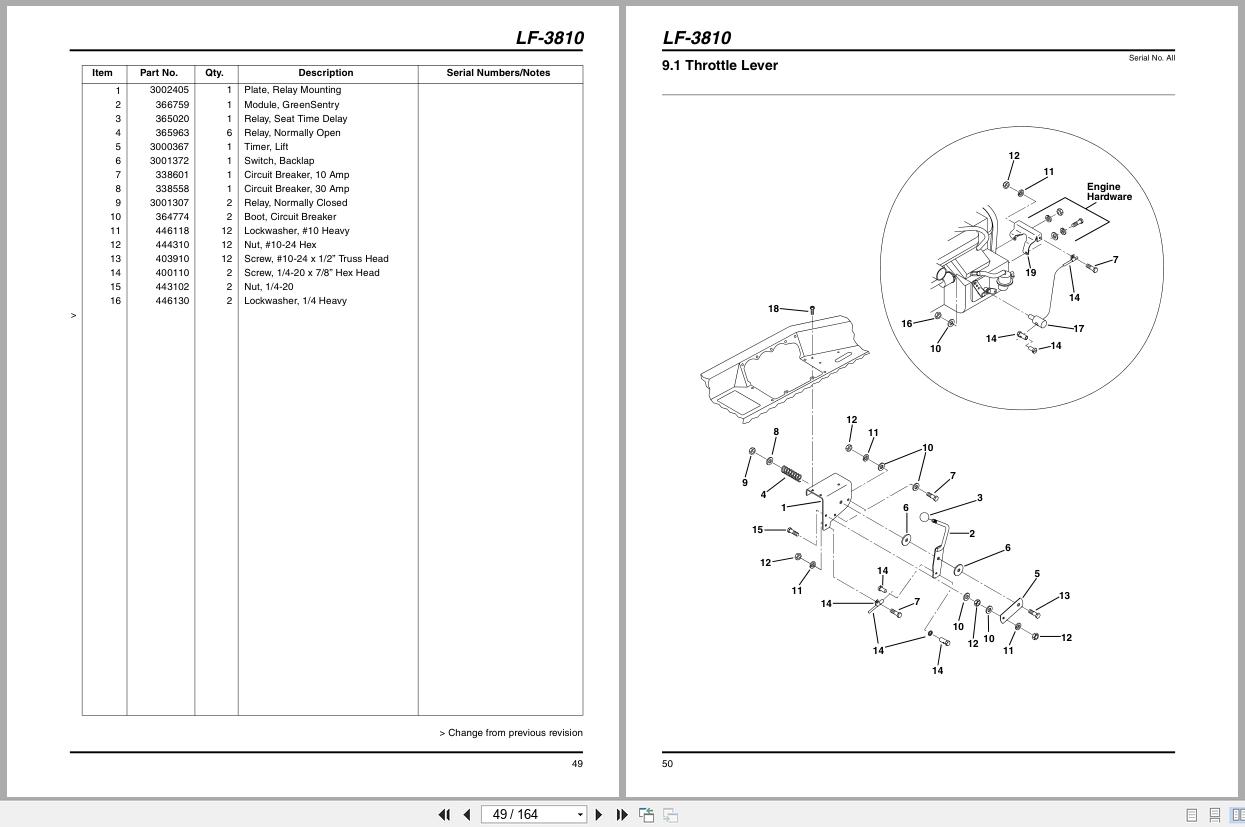
9.1 Throttle Lever
10.1 Traction Pedal
11.1 Lift Valve and Controls
12.1 Front Tires and Brakes
13.1 Frame and Tanks
14.1 Two Wheel Drive Steering
15.1 Four Wheel Drive Steering
16.1 Tilt Steering Assembly
16.2 Tilt Steering Assembly
17.1 Grass Shields
18.1 Battery Tray
19.1 Air Cleaner System
20.1 Radiator and Oil Cooler
21.1 Cooling Hose Routing
21.2 Cooling Hose Routing
22.1 Fuel Hose Routing
23.1 Remote Engine Oil Filter
24.1 Engine Mounting
25.1 Engine Exhaust
26.1 Gear Pump
27.1 Traction Pump Mounting
28.1 Traction Pump Linkage
29.1 Traction Pump Linkage
30.1 Fuel Filter, Reel Valves and Hydraulic Filters
31.1 Front Lift Arms
32.1 Center Lift Arm
33.1 Wing Lift Arms
34.1 Body Harness
35.1 GreenSentry
36.1 Tank Hydraulics
37.1 Reel Valve Hydraulics
38.1 Front Traction and Steering Hydraulics
39.1 Four-Wheel Drive Hydraulic System
40.1 Front Lift Cylinder Hydraulics
41.1 Center Lift Cylinder Hydraulics
42.1 Wing Lift Cylinder Hydraulics
43.1 Center Reel Motor Hydraulics
44.1 Front Reel Motor Hydraulics
45.1 Wing Reel Motor Hydraulics
46.1 Internal Reel Assembly
47.1 External Reel Assembly
48.1 Reel Roller Assembly
49.1 Rear Roller
50.1 Left Reel Assemblies
51.1 Right and Center Reel Assemblies
52.1 Down Pressure Springs
53.1 Skid & Bumper Assembly
54.1 Steering Valve
55.1 Gear Pump Assembly
56.1 Traction Pump Assembly
57.1 Hydro-Centering Assembly
58.1 Rear Wheel Motor
59.1 Front Wheel Motor Assembly
60.1 Fan Motor Assembly
61.1 Reel Motor Assembly
62.1 Manifold Valve
63.1 Disc Brake
64.1 Lift Valve Assembly
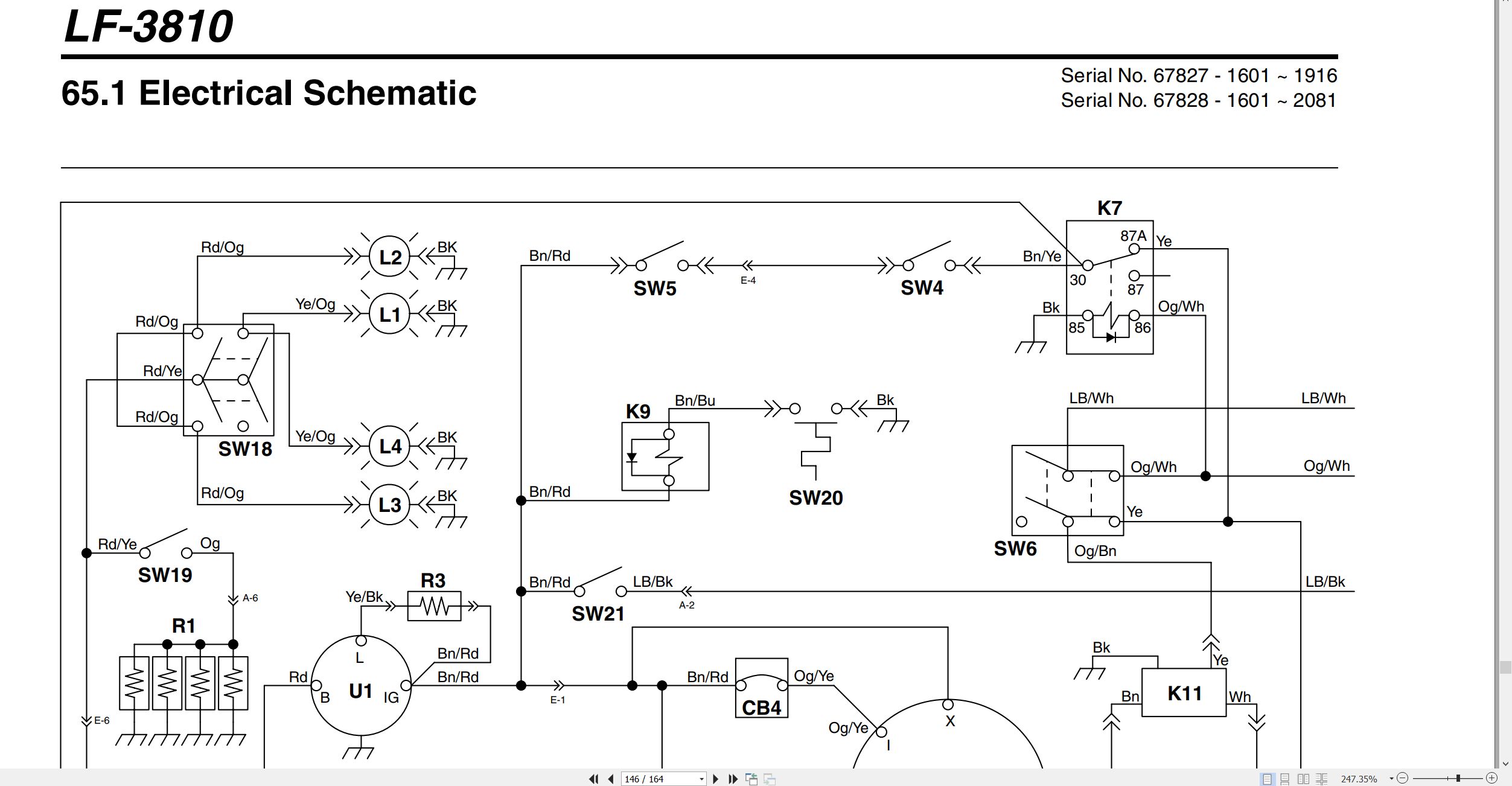
65.1 Electrical Schematic
66.1 Electrical Schematic Legend
67.1 Electrical Schematic Legend
68.1 Electrical Schematic
69.1 Electrical Schematic
70.1 Electrical Schematic Legend
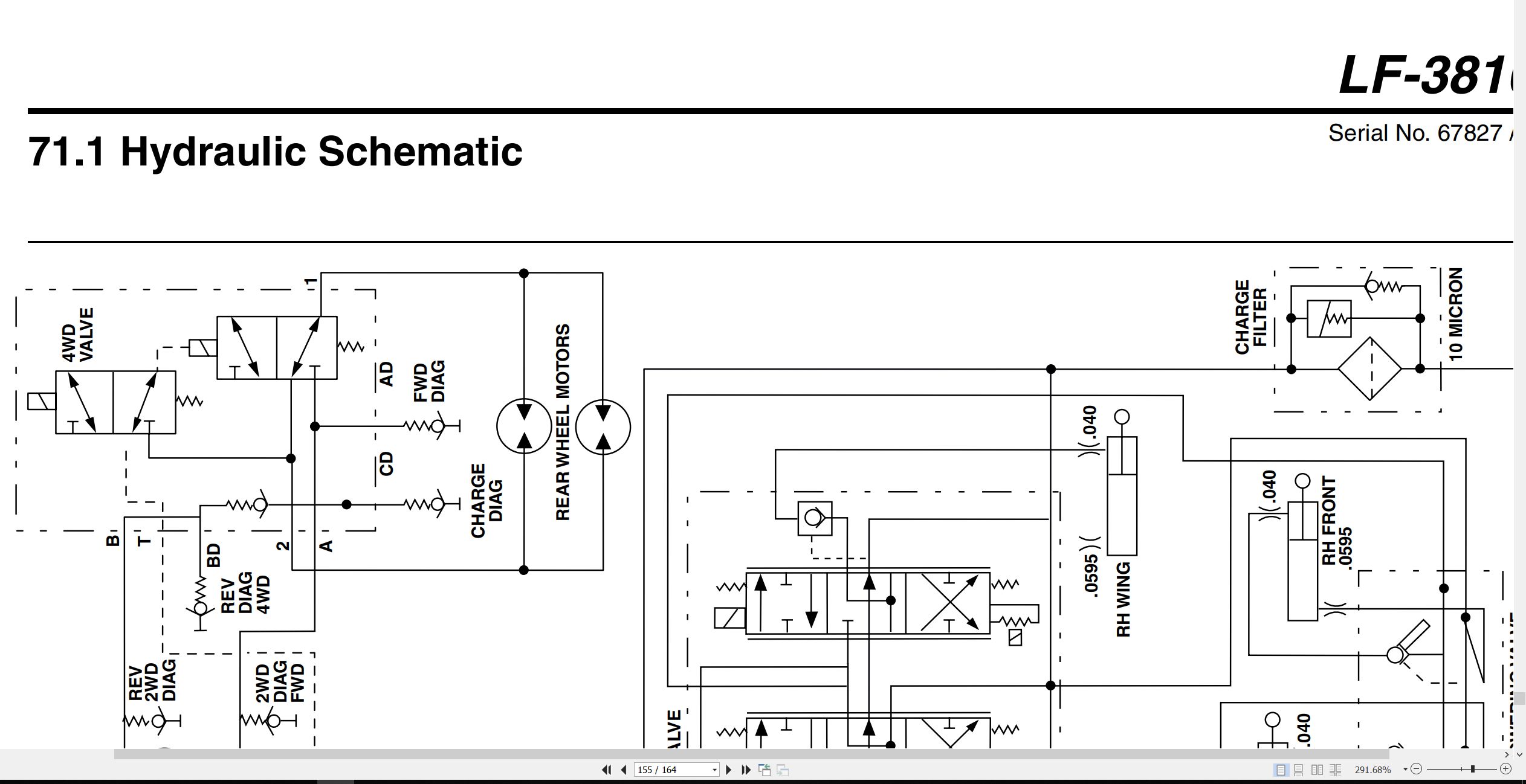
71.1 Hydraulic Schematic
72.1 O-Ring Chart
Related Products
-
Walter Mauser – Kabine Mower LF-3400 to AR-522 Cab Spare Parts List 2011
10 USDSize: 1.29 MBFormat: PDFLanguage: EnglishBrand: Walter Mauser – KabineType of Machine: MowerType of Manual: Spare Parts ListModel: Walter Mauser – Kabine KS-342b For LF 4675, LF 4677, LF 3400, LF 3800, LF 550, LF 570, AR-522 MowerDocument No: 55.865.34.010Publication Date: 2011Number of Pages: 19 Pages
REALEASE :
REALEASE :
-
Ransomes Mower Fairway 250 305 405 Parts Maintenance Manual 24211GR1 2000
10 USDSize: 4.74 MBFormat: PDFLanguage: EnglishBrand: JacobsenType of Machine: Ride On Reel MowerType of Manual: Parts Manual, Hydraulic Diagram, Wiring DiagramModel: Ransomes Fairway 250, Fairway 305, Fairway 405 Ride On Reel MowerSeries: WH, WG, WF – Engine Kubota V1305-E, V1505-E, V1505-TEProduct Codes: LGZZ002, LGPP004, LHAA002Part Number: 24211GR1Publication Date: 2000Number of Pages: 122 Pages
REALEASE :
REALEASE :
-
Ransomes Ride-on Mower T-Plex 185 Parts List 24002G
10 USDSize: 1.86 MBFormat: PDFLanguage: EnglishBrand: RansomesType of Machine: Ride-on MowerType of Manual: Parts ListModel: Ransomes T-Plex 185 Ride-on MowerEngine: kubota D722-EPart Number: 24002GNumber of Pages: 82 Pages
REALEASE :
REALEASE :
-
Ransomes Mower HR-9016T Dealer Manual 2812169-ML1 2001
10 USDSize: 4.32 MBFormat: PDFLanguage: French, German, Italian, EnglishBrand: RansomesType of Machine: MowerType of Manual: Dealer ManualModel: Ransomes HR-9016 Turbo Mower4WD 70526, 4WD 70527 with ROPSEngine: Detroit Diesel D704LTPart Number: 2812169-ML1Publication Date: 2001Number of Pages: 138 Pages
REALEASE :
REALEASE :
-
Ransomes Ride-on Mower T-Plex 185 Operation Safety Manual 24034G 2000 ML
10 USDSize: 2.14 MBFormat: PDFLanguage: English, French, Dutch, German, ItalianBrand: RansomesType of Machine: Ride-on MowerType of Manual: Operation Manual, Safety Manual, Hydraulic Diagram, Wiring DiagramModel: Ransomes T-Plex 185 Ride-on MowerSeries: UL -26” Cutting Unit, US -30” Cutting Unit – Engine Kubota D722BProduct codes: LGXX006, LGXX008Part Number: 24034GPublication Date: 2000Number of Pages: 164 Pages
REALEASE :
REALEASE :
-
Ransomes Ride-on Mower T-Plex 185 Parts Manual 24071 2000
10 USDSize: 2.94 MBFormat: PDFLanguage: EnglishBrand: RansomesType of Machine: Ride-on MowerType of Manual: Parts ManualModel: Ransomes T-Plex 185 Ride-on MowerSeries: UL -26” Cutting Unit, US -30” Cutting Unit – Engine Kubota D722BProduct Codes: LGXX006, LGXX008Part Number: 24071Publication Date: 2000Number of Pages: 110 Pages
REALEASE :
REALEASE :
-
Ransomes Ride-on Mower T-Plex 185 Operation Safety Manual 23993G EN DA SV
10 USDSize: 5.05 MBFormat: PDFLanguage: English, Swedish, DanishBrand: RansomesType of Machine: Ride-on MowerType of Manual: Operation Manual, Safety Manual, Wiring Diagram, Hydraulic DiagramModel: Ransomes T-Plex 185 Ride-on MowerSerial Number: STPart Number: 23993GNumber of Pages: 83 Pages
REALEASE :
REALEASE :
-
TEXTRON Engine Suzuki 660CC EFI Service Manual 4115756
20 USDSize: 4.05 MBFormat: PDFLanguage: EnglishBrand: TEXTRONType of Machine: EngineType of Manual: Service ManualModel: TEXTRON Suzuki 660CC EFI EnginePart Number: 4115756Number of Pages: 115 PagesContents:Section 1 Electronic Fuel Injection TheorySection 2 Periodic MaintenanceSection 3 TroubleshootingSection 4 EFI EngineSection 5 Voltage TestingSection 6 Component Testing
REALEASE :
REALEASE :