
1 ITEMVIEW CART

Total: 80.00
Expert Support
Full Speed
100% Working
10 USD
Contents:
Safety
1.1 Operating Safety
1.2 Important Safety Notes
Specifications
2.1 Product Identification
2.2 Engine
2.3 Cutting Units:
2.4 Tractor
2.5 Weights and Dimensions
2.6 Accessories & Support Literature
Adjustments
3.1 General
3.2 Fan Belt (Diesel Engines)
3.3 Pump Drive Belt
3.4 Bedknife-To-Reel
3.5 Bedknife Adjustment
3.6 Cutting Height
3.7 Reel Bearing
3.8 Choke Control (Gas Engines)
3.9 Mow / Transport Switch
3.10 Anti-Sway Tether
3.11 Parking Brake Adjustment
3.12 Parking Brake Switch
3.13 Neutral Start Switch
3.14 3WD Switch
3.15 Reel Proximity Switch
3.16 Installing Cutting Units
3.17 Torque Specification
3.18 Torque Requirements
Maintenance
4.1 General
4.2 Engine
4.3 Engine Oil
4.4 Gas Engine Air Filter
4.5 Diesel Air Filter
4.6 Fuel
4.7 Fuel System
4.8 Battery
4.9 Jump Starting
4.10 Charging Battery
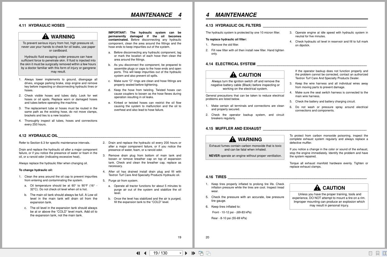
4.11 Hydraulic Hoses
4.12 Hydraulic Oil
4.13 Hydraulic Oil Filters
4.14 Electrical System
4.15 Muffler and Exhaust
4.16 Tires
4.17 Wheel Mounting Procedure
4.18 Care and Cleaning
4.19 Radiator (Diesel Engines)
4.20 Backlapping
4.21 Storage
Troubleshooting
5.1 General
Maintenance & Lubrication Charts
6.1 General
6.2 Lubrication Chart
6.3 Maintenance Charts
Parts Catalog
7.1 Table Of Contents
1.1 Decals
2.1 Hood
3.1 Hood, Cowling, and Console
4.1 Operator’s Platform
5.1 Instrument Panel
6.1 Gasoline Engine Control Console
7.1 Diesel Engine Control Console
8.1 Steering Tower and Gauges
9.1 Traction Pedal Linkage
10.1 Parking Brake
11.1 Front Wheel Motors and Brakes
12.1 Lift Mow Controls
13.1 Seat
14.1 Baseframe and Lift Arms
15.1 Lift Linkage
16.1 Steering Axle-2WD Units
17.1 Steering Axle-3WD Units
18.1 Steering Tower
19.1 Gasoline Fuel Lines
20.1 Diesel Fuel Lines
21.1 Air Duct and Oil Cooler
22.1 Radiator
23.1 Gasoline Engine Mounting
24.1 Gasoline Engine
25.1 Diesel Engine Mounting
26.1 Diesel Engine
27.1 Pump Assembly
28.1 Rear Frame Hydraulic Components
29.1 Hydraulic Tanks
30.1 Pump Hydraulics
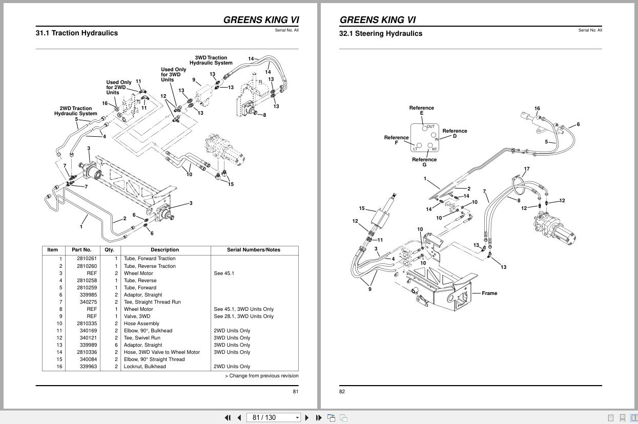
31.1 Traction Hydraulics
32.1 Steering Hydraulics
33.1 Lift Hydraulics
34.1 Front Reel Hydraulics
34.2 Front Reel Hydraulics
35.1 Rear Reel and Return Hydraulics
35.2 Rear Reel and Return Hydraulics
36.1 Hydraulic Hose Clamps
36.2 Hydraulic Hose Clamps
37.1 Circuit Breaker Mounting
38.1 Circuit Breaker Mounting
39.1 Electrical Routing
40.1 Reel
41.1 Reel (Continued)
42.1 Rear Roller
43.1 Rear Roller
44.1 Hydrostatic Pump
45.1 Wheel Motor
46.1 Steering Valve
47.1 3WD Valve
48.1 Lift Valve
49.1 Wheel and Tire
50.1 Lift Cylinder
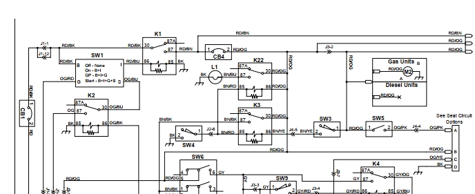
51.1 Electrical Schematic
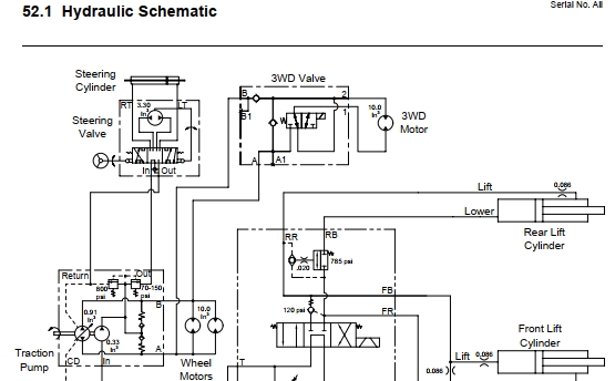
52.1 Hydraulic Schematic
53.1 O-Ring Chart

REALEASE :
REALEASE :

REALEASE :
REALEASE :

REALEASE :
REALEASE :

REALEASE :
REALEASE :

REALEASE :
REALEASE :

REALEASE :
REALEASE :

REALEASE :
REALEASE :

REALEASE :
REALEASE :
 Automotive - Heavy Equipment - Truck & Bus - Forklift - Crane