
0 ITEMSVIEW CART


✓
Expert Support
✓
Full Speed
✓
100% Working
Jacobsen Mower Greens King VI Parts Maintenance Manual 4127225-B 2006
Size: 8.15 MB
Format: PDF
Language: English
Brand: Jacobsen
Type of Machine: Mower
Type of Manual: Parts List, Maintenance Manual, Hydraulic Diagram, Wiring Diagram
Model: Jacobsen Mower
Greens King VI 62375 – 1862G, Briggs Vanguard Engine, 2WD
Greens King VI 62376 – 1862G, Briggs Vanguard Engine, 3WD
Greens King VI 62377 – 1962D, Kubota D662-EB Engine, 2WD
Greens King VI 62378 – 1962D, Kubota D662-EB Engine, 3WD
Part Number: 4127225-B
Publication Date: 2006
Number of Pages: 132 Pages
10 USD
- Description
Description
Contents:
1.1 Operating Safety
1.2 Important Safety Notes
2.1 Product Identification
2.2 Engine
2.3 Cutting Units:
2.4 Tractor
2.5 Weights and Dimensions
2.6 Accessories & Support Literature
3.1 General
3.2 Fan Belt (Diesel Engines)
3.3 Pump Drive Belt
3.4 Bedknife-To-Reel
3.5 Bedknife Adjustment
3.6 Cutting Height
3.7 Reel Bearing
3.8 Choke Control (Gas Engines)
3.9 Mow / Transport Switch
3.10 Anti-Sway Tether
3.11 Parking Brake Adjustment
3.12 Parking Brake Switch
3.13 Neutral Start Switch
3.14 3WD Switch
3.15 Reel Proximity Switch
3.16 Installing Cutting Units
3.17 Torque Specification
3.18 Torque Requirements
4.1 General
4.2 Engine
4.3 Engine Oil
4.4 Gas Engine Air Filter
4.5 Diesel Air Filter
4.6 Fuel
4.7 Fuel System
4.8 Battery
4.9 Jump Starting
4.10 Charging Battery
4.11 Hydraulic Hoses
4.12 Hydraulic Oil
4.13 Hydraulic Oil Filters
4.14 Electrical System
4.15 Muffler and Exhaust
4.16 Tires
4.17 Wheel Mounting Procedure
4.18 Care and Cleaning
4.19 Radiator (Diesel Engines)
4.20 Backlapping
4.21 Storage
5.1 General
6.1 General
6.2 Lubrication Chart
6.3 Maintenance Charts
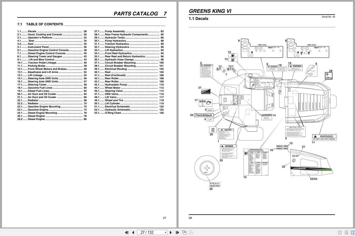
7.1 Table Of Contents
1.1 Decals
2.1 Hood, Cowling and Console
3.1 Operator’s Platform
4.1 Seat
4.2 Seat
5.1 Instrument Panel
6.1 Gasoline Engine Control Console
7.1 Diesel Engine Control Console
8.1 Steering Tower and Gauges
9.1 Lift and Mow Control
10.1 Traction Pedal Linkage
11.1 Parking Brake
12.1 Front Wheel Motors and Brakes
13.1 Baseframe and Lift Arms
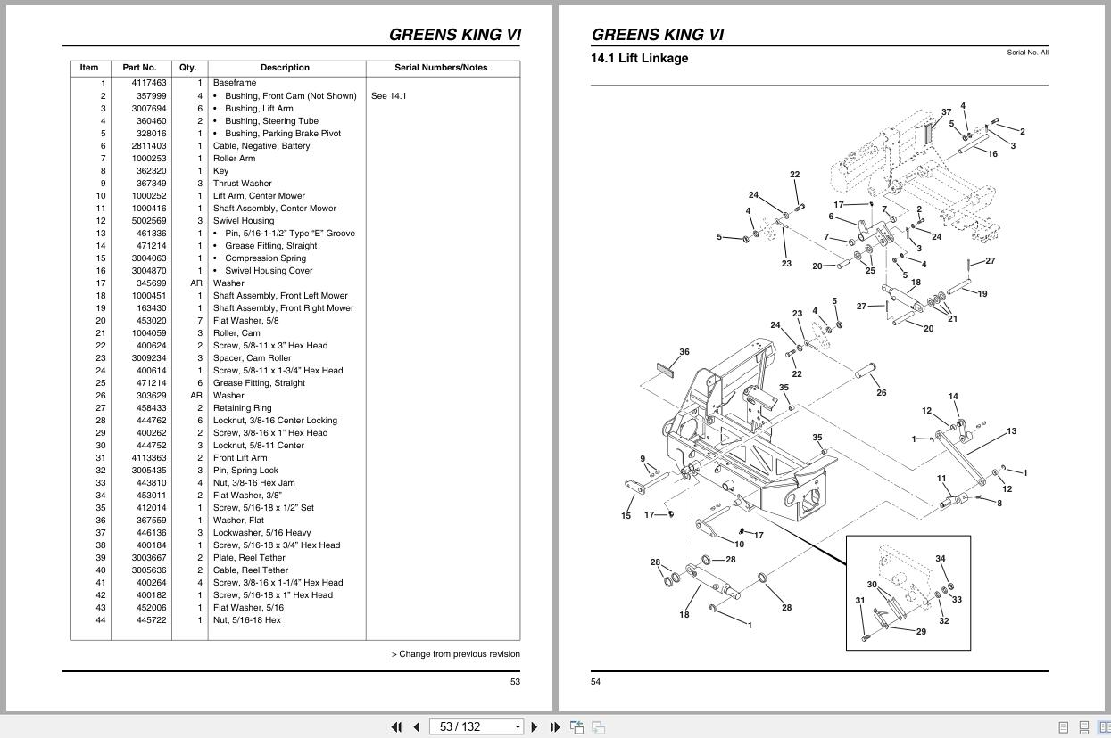
14.1 Lift Linkage
15.1 Steering Axle-2WD Units
16.1 Steering Axle-3WD Units
17.1 Steering Tower
18.1 Gasoline Fuel Lines
19.1 Diesel Fuel Lines
20.1 Air Duct and Oil Cooler
21.1 Air Duct and Oil Cooler
22.1 Radiator
22.2 Radiator
23.1 Gasoline Engine Mounting
24.1 Gasoline Engine
25.1 Diesel Engine Mounting
26.1 Diesel Engine
26.2 Diesel Engine
27.1 Pump Assembly
28.1 Rear Frame Hydraulic Components
29.1 Hydraulic Tanks
30.1 Pump Hydraulics
31.1 Traction Hydraulics
32.1 Steering Hydraulics
33.1 Lift Hydraulics
34.1 Front Reel Hydraulics
35.1 Rear Reel and Return Hydraulics
36.1 Hydraulic Hose Clamps
37.1 Circuit Breaker Mounting
38.1 Circuit Breaker Mounting
39.1 Electrical Routing
40.1 Reel
41.1 Reel (Continued)
42.1 Rear Roller
43.1 Rear Roller
44.1 Hydrostatic Pump
45.1 Wheel Motor
46.1 Steering Valve
47.1 3WD Valve
48.1 Lift Valve
49.1 Wheel and Tire
50.1 Lift Cylinder
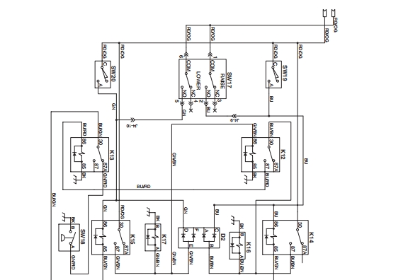
51.1 Electrical Schematic
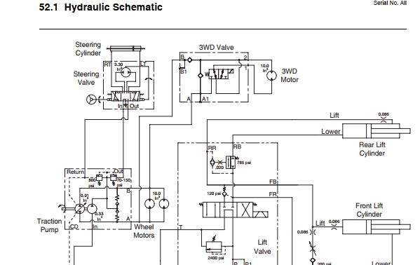
52.1 Hydraulic Schematic
53.1 O-Ring Chart
Related Products
-
Ransomes Ride-on Mower T-Plex 185 Parts Manual 24071 2000
10 USDSize: 2.94 MBFormat: PDFLanguage: EnglishBrand: RansomesType of Machine: Ride-on MowerType of Manual: Parts ManualModel: Ransomes T-Plex 185 Ride-on MowerSeries: UL -26” Cutting Unit, US -30” Cutting Unit – Engine Kubota D722BProduct Codes: LGXX006, LGXX008Part Number: 24071Publication Date: 2000Number of Pages: 110 Pages
REALEASE :
REALEASE :
-
Walter Mauser – Kabine Mower LF-3400 to AR-522 Cab Spare Parts List 2011
10 USDSize: 1.29 MBFormat: PDFLanguage: EnglishBrand: Walter Mauser – KabineType of Machine: MowerType of Manual: Spare Parts ListModel: Walter Mauser – Kabine KS-342b For LF 4675, LF 4677, LF 3400, LF 3800, LF 550, LF 570, AR-522 MowerDocument No: 55.865.34.010Publication Date: 2011Number of Pages: 19 Pages
REALEASE :
REALEASE :
-
TEXTRON Engine Suzuki 660CC EFI Service Manual 4115756
20 USDSize: 4.05 MBFormat: PDFLanguage: EnglishBrand: TEXTRONType of Machine: EngineType of Manual: Service ManualModel: TEXTRON Suzuki 660CC EFI EnginePart Number: 4115756Number of Pages: 115 PagesContents:Section 1 Electronic Fuel Injection TheorySection 2 Periodic MaintenanceSection 3 TroubleshootingSection 4 EFI EngineSection 5 Voltage TestingSection 6 Component Testing
REALEASE :
REALEASE :
-
Ransomes Ride-on Mower T-Plex 185 Operation Safety Manual 24034G 2000 ML
10 USDSize: 2.14 MBFormat: PDFLanguage: English, French, Dutch, German, ItalianBrand: RansomesType of Machine: Ride-on MowerType of Manual: Operation Manual, Safety Manual, Hydraulic Diagram, Wiring DiagramModel: Ransomes T-Plex 185 Ride-on MowerSeries: UL -26” Cutting Unit, US -30” Cutting Unit – Engine Kubota D722BProduct codes: LGXX006, LGXX008Part Number: 24034GPublication Date: 2000Number of Pages: 164 Pages
REALEASE :
REALEASE :
-
Ransomes Mower Fairway 250 305 405 Parts Maintenance Manual 24211GR1 2000
10 USDSize: 4.74 MBFormat: PDFLanguage: EnglishBrand: JacobsenType of Machine: Ride On Reel MowerType of Manual: Parts Manual, Hydraulic Diagram, Wiring DiagramModel: Ransomes Fairway 250, Fairway 305, Fairway 405 Ride On Reel MowerSeries: WH, WG, WF – Engine Kubota V1305-E, V1505-E, V1505-TEProduct Codes: LGZZ002, LGPP004, LHAA002Part Number: 24211GR1Publication Date: 2000Number of Pages: 122 Pages
REALEASE :
REALEASE :
-
Ransomes Mower HR-9016T Dealer Manual 2812169-ML1 2001
10 USDSize: 4.32 MBFormat: PDFLanguage: French, German, Italian, EnglishBrand: RansomesType of Machine: MowerType of Manual: Dealer ManualModel: Ransomes HR-9016 Turbo Mower4WD 70526, 4WD 70527 with ROPSEngine: Detroit Diesel D704LTPart Number: 2812169-ML1Publication Date: 2001Number of Pages: 138 Pages
REALEASE :
REALEASE :
-
Ransomes Ride-on Mower T-Plex 185 Operation Safety Manual 23993G EN DA SV
10 USDSize: 5.05 MBFormat: PDFLanguage: English, Swedish, DanishBrand: RansomesType of Machine: Ride-on MowerType of Manual: Operation Manual, Safety Manual, Wiring Diagram, Hydraulic DiagramModel: Ransomes T-Plex 185 Ride-on MowerSerial Number: STPart Number: 23993GNumber of Pages: 83 Pages
REALEASE :
REALEASE :
-
Ransomes Ride-on Mower T-Plex 185 Parts List 24002G
10 USDSize: 1.86 MBFormat: PDFLanguage: EnglishBrand: RansomesType of Machine: Ride-on MowerType of Manual: Parts ListModel: Ransomes T-Plex 185 Ride-on MowerEngine: kubota D722-EPart Number: 24002GNumber of Pages: 82 Pages
REALEASE :
REALEASE :