
0 ITEMSVIEW CART


✓
Expert Support
✓
Full Speed
✓
100% Working
Kubota Loader LA514 Assembly Instructions
Size: 1.81 MB
Format: PDF
Language: English
Brand: Kubota
Type of Machine: Loader
Type of Manual: Assembly Instructions
Model: Kubota LA514 Loader
Number of Pages: 30 Pages
10 USD
- Description
Description
Contents:
ASSEMBLY INSTRUCTIONS
TO THE DEALER
SAFETY
UNPACKING AND CHECKING PARTS
B Unpacking Wooden Crate
1. Cutting metal bands (if two are banded together). Metal bands hold the two crates together as …
2. Unpacking the crates
(1) Hook a hoist to the 4 corners of the crate and raise the hoist cable until taut. This serves …
(2) Saw the crate as indicated in the figure 1.
A Sawing outside the indicated area may damage the loader or accessory parts.
A Be sure that the crate is free of other obstructions (e.g. nails, staples and etc.).
(3) Raise the upper part of the crate and remove from the immediate area.
(4) Remove the remaining slats from the crate. These are indicated by the oblique lines in Figure…
B Checking Parts
TRACTOR PREPARATION
ASSEMBLY
B Boom Assembly
To avoid personal injury:
A Do not operate or mount loader without quick attach or bucket installed to loader. Damage may o…
1. Attach the bucket to the boom and bucket links as shown.
2. Raise the boom until the stands can be rotated.
3. Remove the spring pins holding the stands to the boom.
4. Rotate the stands until the pin on the stand and hole in the boom are aligned. Then slide the …
B Boom Assembly with Quick Hitch (Option)
1. Attach the quick hitch to the boom and bucket links as shown.
2. Raise the boom until the stands can be rotated.
3. Remove the spring pins holding the stands to the boom.
4. Rotate the stands until the pin on the stand and hole in the boom are aligned. Then slide the …
B Level Indicator (LA514)
1. Attach the level indicator.
B Main Frame
1. Remove plastic plugs and any excess paint from tractor body bolt locations.
2. Attach the main frame LH and RH to the flywheel housing and tractor frame as shown.
1. Remove the air conditioner hose clamp from the side of the clutch case.
2. Install the loader main frame, and using the cord band, secure the air conditioner hoses out o…
A When installing the main frame, be careful not to get the air conditioner hoses caught. With th…
3. Secure the controller cable out of contact with the sub frame, using the cord band.
B Sub Frame
1. Attach the sub frame to the main frame as shown.
A There are the three holes left at the sub frame. These three holes will be used when installing…
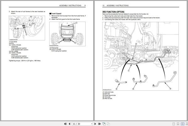
2. Attach the rear of sub frames to the rear brackets as shown.
B Front Guard
1. Remove the front bumper from the front axle frame, if equipped.
2. Attach the front guard to the front axle frame.
3RD FUNCTION (OPTION)
B Inlet Tube Disassembly
1. Remove the rear tire RH and fender RH. Remove also the front loader main frame and sub frame, …
2. Drain the oil completely from the drain plug.
3. Remove the coupler stay mounting bolts.
4. Loosen the valve tubes.
5. Disconnect the valve tank tube.
A Be careful not to lose the copper packings when disconnecting the tractor hydraulic tubes.
6. Remove the brake rod RH.
7. Remove the bearing flange and joint cover.
8. Remove the bolt and draw out the universal joint from the joint shaft.
A Pull the universal joint out of the joint shaft. Temporarily reapply the bolt in its original p…
9. Disconnect the inlet tube.
A O-ring will be used again. Be sure to handle it with care and not to lose it.
B Inlet 3rd Tube Assembly
1. Connect the inlet 3rd tube and inlet hose. Temporarily connect the inlet hose. Do not tighten …
(1) Be sure to put the O-ring to the inlet 3rd tube.
(2) Be sure to put the rubber in between the inlet 3rd tube and the metal fitting.
A Tighten the bolts to their respective specified torques.
2. Connect the tank tube and tank hose.
A Orient the tank hose toward the tractor front, as shown below. Make sure the hose is out of con…
3. Temporarily connect the power beyond tube and power beyond hose in their respective positions.
4. Attach the metal fitting and secure the tank tube and power beyond tube.
A With the power beyond tube and tank tube temporarily connected and secured with the metal fitti…
5. Tighten the power beyond tube and power beyond hose.
6. Attach the brake rod RH.
A Split the split pins on both sides as shown below.
A Tighten the bolts to their respective specified torques.
7. Remove the temporarily applied bolt. Fit the universal joint into the joint shaft. Temporarily…
8. Attach the bearing flange and joint cover and tighten them with bolts.
A Before tightening the bolts, make sure the joint is out of contact with nearby parts.
9. Attach the front loader and main frame RH.
(1) Keep all the bolts temporarily tight.
(2) See “Main Frame” section for setting up.
10. Tighten the valve tubes.
11. Attach 3rd function assembly to the frond loader and sub frame RH.
12. Connect hoses to the 3rd function assembly.
A Tighten the bolts to their respective specified torques.
13. Install the coupler stay and connect the hydraulic hose A and 3rd function assembly to the co…
B 3rd Function Lever Section (ROPS Model)
1. Remove the original lever.
2. Detach the grip and lever boot from the original lever.
3. Cut the detached lever boot as shown below.
4. Remove the bolt and nut, and then take out the lever assembly.
A Tighten the bolts to their respective specified torques.
5. Remove the sleeve and rod from the lever assembly and fit them to the control lever 2.
(1) Make sure to put the sleeve to the control lever 2.
(2) Apply Loctite 271 or equivalent in fitting the rod into position.
6. Attach the lever boot to the control lever assembly.
A Make sure not to get the lever harness twisted.
7. Temporarily attach the control lever 2 to the control lever assembly.
(1) Screw in the control lever assembly as deep as possible.
(2) Do not yet get the nut locked. (3) Apply Loctite 271 or equivalent in fitting the rod into po…
8. Install the 3rd function lever assembly.
A Apply Loctite 271 or equivalent in fitting the rod into position.
C Wire Harness
A Connect the wire harness couplers of the 3rd function control lever to their respective same-co…
9. Connect the 3rd function harness with tractor harness.
10. Pass the 3rd function harness through the lever console. Connect the 3rd function control lev…
(1) Using the cord band, secure the 3rd function harness and the tractor harness onto the floor s…
(2) Move the control lever to make sure it does not catch or drag the harnesses.
A Tighten the bolts to their respective specified torques.
11. Connect the harness to the solenoid valve harness and attach the cover.
12. Attach the tractor fender RH.
A With the fender in place, move the lever to make sure it is out of contact with the fender and …
13. Attach the rear tire RH.
14. Apply rubber type bond to the boot and attach the boot to the lever guide.
B 3rd Function Lever Section (CAB Model)
1. Remove the original lever.
2. Detach the lever boot from the original lever.
3. Cut the detached lever boot as shown below.
4. Detach the upper console.
5. Detach the lower console.
A Tighten the bolts to their respective specified torques.
6. Remove the rubber cap from the hole under the seat. Make the 18 mm diameter hole.
A Just scrape the hole large enough to pass the harness, if desired.
7. Attach the detached lever boot to the control lever assembly (CAB) and install it to the tractor.
8. Slit the rubber cap crosswise and pass the harness through it.
9. Lay the harness (at the solenoid valve side) out of the cabin. Then make necessary connections…
A Make sure the harness is out of contact with other parts and not too tight.
C Wire Harness
A Connect the wire harness couplers of the 3rd function control lever to their respective same-co…
10. Put the lower and upper consoles back into position in the reverse order of removal.
A Make sure the harness and other parts are not caught between the upper and lower consoles.
A Move the control lever and make sure the harness is not caught by the lever or other parts and …
11. Connect the harness to the solenoid valve harness and attach the cover.
B 3rd Function Boom Section
1. Attach the coupler stay to the boom.
2. Fit the 3rd function tube 1 and 2 to the boom.
3. Connect the 3rd function tube 1 and 2 to the mid hydraulic hose.
4. Front hydraulic valve main switch Push the front hydraulic valve main switch (1) to engage the…
5. Activation switch
(1) When pressing the “A” button, hydraulic oil will come out of the port A and return through th…
(2) When pressing the “B” button hydraulic oil will come out of the port B and return through the…
6. Push the front hydraulic valve main switch again to disengage the front hydraulic valve, and t…
PRE-OPERATION CHECK
B Lubrication
B Transmission Fluid
A To check the tractor transmission fluid level, lower the bucket to the ground and lower the 3-p…
B Hydraulic Hose Route
ESTIMATED ASSEMBLY TIME
TIGHTENING TORQUE OF BOLTS AND NUTS
Related Products
-
Kubota Gasoline Diesel Engine Collection Workshop Service Manual Information PDF DVD
Original price was: 500.300Current price is: 300. USDKubota Gasoline & Diesel Engine 4.27GB Collection Workshop Service Manual PDF DVDSize: 4.27 GB (PDF Files)Language: ENFormat: PDFBrand: KubotaTypes of Vehicle: Gasoline & Diesel EngineTypes of Manuals: Workshop Service ManualQuantity of CD: 1 DVDOS: All WindowsHigh-Speed link DownloadHot-40%
REALEASE :
01.07.2022
REALEASE :
01.07.2022
-
Kubota EPC KE FR 10.2021 Spare Parts Catalog Program
Price range: 70 through 150 USDSize: 8.7GB (WinRAR Files)Type of Vehicle: Kubota tractors, Kubota Construction Machinery, Kubota Power Products, Kubota Utility VehicleType of program: Spare Parts CatalogDatabase + Interface Languages: English, French (KE FR)OS: Windows 7, Windows 8, Windows 10 32 & 64-bit (Tested on Windows 10 Pro 22h2 64bit)Date update: 10.2021Instruction: How To InstallHot
REALEASE :
11.05.2022
REALEASE :
11.05.2022
-
Kubota Wheel Loader RT270 RT270D Spare Parts Catalog EN FR
20 USDSize: 92.65 MBFormat: PDFLanguage: French, EnglishBrand: KubotaType of Machine: Wheel LoaderType of Manual: Spare Parts CatalogModel: Kubota RT270 RT270D Wheel LoaderNumber of Pages: 132 Pages
REALEASE :
REALEASE :
-
Kubota Wheel Loader RT280 RT280D Spare Parts Catalog EN FR
20 USDSize: 95.70 MBFormat: PDFLanguage: French, EnglishBrand: KubotaType of Machine: Wheel LoaderType of Manual: Spare Parts CatalogModel: Kubota RT280 RT280D Wheel LoaderNumber of Pages: 122 Pages
REALEASE :
REALEASE :
-
Kubota Engine V3800-CR-TE4B V3800-CR-TTE4B Diagnosis Manual 9Y110-02070 2013
20 USDSize: 17.18 MBFormat: PDFLanguage: EnglishBrand: KubotaType of Machine: EngineType of Manual: Diagnosis Manual – Common Rail SystemModel: Kubota V3800-CR-TE4B ; V3800-CR-TTE4B (Hyundai) EnginePart Number: 9Y110-02070Publication Date: 2013Number of Pages: 349 Pages
REALEASE :
REALEASE :
-
Kubota Engine 03-CR-E4 03-CR-TE4 03-CR-TE4BG 03-CR-TIE4 Diagnosis Manual 9Y110-02091 2015
20 USDSize: 8.20 MBFormat: PDFLanguage: EnglishBrand: KubotaType of Machine: EngineType of Manual: Diagnosis Manual – Common Rail SystemModel: Kubota 03-CR-E4 ; 03-CR-TE4 ; 03-CR-TE4BG ; 03-CR-TIE4 (DOC only) EnginePart Number: 9Y110-02091Publication Date: 2015Number of Pages: 317 Pages
REALEASE :
REALEASE :
-
Kubota Wheel Loader RW30 Spare Parts Catalog EN FR
20 USDSize: 61.86 MBFormat: PDFLanguage: French, EnglishBrand: KubotaType of Machine: Wheel LoaderType of Manual: Spare Parts CatalogModel: Kubota RW30 Wheel LoaderNumber of Pages: 171 Pages
REALEASE :
REALEASE :
-
Kubota Wheel Loader RW25 Spare Parts Catalog EN FR
20 USDSize: 45.40 MBFormat: PDFLanguage: French, EnglishBrand: KubotaType of Machine: Wheel LoaderType of Manual: Spare Parts CatalogModel: Kubota RW25 Wheel LoaderNumber of Pages: 152 Pages
REALEASE :
REALEASE :