")


Expert Support
Full Speed
100% Working
NIFTYLIFT Articulating Boom Lifts SP34 35305 Operating Parts Manual And Diagram 2017
30 USD
- Description
Description
List of Files:
01_DIAGRAM LIFTING POINTS HR10 & 12 D80461 (issue 004) 35305.pdf (2 Pages)
02_HOSE DIAGRAM HR12DE 4WD D80849 (issue 001) 35305.pdf (1 Pages)
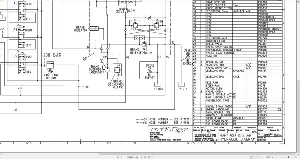
03_HYDRAULIC DIAGRAM HR12DE 4WD D80850 (issue 015) 35305.pdf (1 Pages)
04_ELECTRICAL SCHEMATIC HR12 4WD D80928 (issue 009) 35305.pdf (4 Pages)
05_HR12 (SP34) 4×4 PARTS MANUAL M50191 (issue 008) 35305.pdf (92 Pages)
Contents:
chassis assembly
1.1 Base assembly
1.2 Bonnets/Covers/Guards
1.3 Front axle assembly
1.4 Power pack
1.5 Drive control valve
1.6 Diesel engine (Part 1)
1.7 Diesel engine (Part 2)
1.8 Diesel box
1.9 Anderson connector
superstructure
2.1 Control station – Base
2.2 Slew assembly
2.3 Control valve assembly (3 spool)
2.4 Button box assembly
2.5 Control box
2.6 Dual voltage charger box
2.7 Battery charger
boom assemblies
3.1 Booms assembly
3.2 Lift cylinder
3.3 Levelling cylinder
3.4 Telescope cylinder
3.5 Energy chain
cage assembly
4.1 Cage assembly
4.2 SiOPS assembly
4.3 Cage weigh assembly – Load Cell
4.4 Control box – Cage
4.5 Control valve – Cage
labelling
5.1 Label locations
5.2 Label locations SP34 (USA)
Labels 1 to 34
Labels 35 to 43
06_Kubota D722 Z482 Operators Manual And Wiring Diagram M50291 (issue 002) 35305 1J090-8916-1.pdf (39 Pages)
Contents:
E.pdf
SAFE OPERATION
SERVICING OF THE ENGINE
NAMES OF PARTS
PRE-OPERATION CHECK
BREAK-IN
DAILY CHECK
To prevent trouble from occurring, it is important to know the conditions of the engine well. Che…
OPERATING THE ENGINE
STARTING THE ENGINE(NORMAL)
COLD WEATHER STARTING
STOPPING THE ENGINE
CHECKS DURING OPERATION
REVERSED ENGINE REVOLUTION AND REMEDIES
MAINTENANCE
SERVICE INTERVALS
PERIODIC SERVICE
FUEL
ENGINE OIL
RADIATOR
AIR CLEANER
ELECTRIC WIRING
FAN BELT
CARRIAGE AND STORAGE
CARRIAGE
STORAGE
TROUBLESHOOTING
If the engine does not function properly, use the following chart to identify and correct the cause.
SPECIFICATIONS
WIRING DIAGRAMS
07_SP26 34 OPERATING MANUAL (USA) M50416 (issue 002) 35305.pdf (42 Pages)
Contents:
Blank Page
Related Products
-
NIFTYLIFT Towable Boom Lifts TM64 56064 Operating Service Parts Manual And Diagram 2023
40 USD -
NIFTYLIFT Towable Boom Lifts TM64 55060 Operating Service Parts Manual And Diagram 2023
40 USD -
NIFTYLIFT Towable Boom Lifts TM64 52414 Operating Service Parts Manual And Diagram 2022
40 USD -
NIFTYLIFT Towable Boom Lifts TM50 56687 Operating Service Parts Manual And Diagram 2025
50 USD -
NIFTYLIFT Towable Boom Lifts TM50 56720 Operating Service Parts Manual And Diagram 2025
50 USD -
NIFTYLIFT Towable Boom Lifts TM50 58728 Operating Service Parts Manual And Diagram 2025
50 USD -
NIFTYLIFT Towable Boom Lifts TM50 57219 Operating Service Parts Manual And Diagram 2025
50 USD -
NIFTYLIFT Towable Boom Lifts TM64 55045 Operators Service Manual Diagram 2023
40 USD