
1 ITEMVIEW CART

Total: 20.00
Expert Support
Full Speed
100% Working
15 USD
Contents:
Platform Related Parts
Figure 1.1 Main Platform And Railings
Figure 1.2 4 Ft. Roll-out Extension Platform Assembly
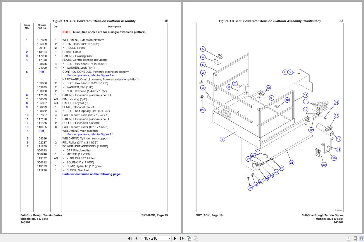
Figure 1.3 4 Ft. Powered Extension Platform Assembly
Figure 1.4 Powered Extension Platform Control Console Assembly
Figure 1.5 Powered Extension Platform Cylinder Assembly
Figure 1.6 Powered Extension Platform Electrical Panel
Figure 1.7 Hydraulic Hose Connections – Single Powered Extension Platform
Figure 1.8 Hydraulic Hose Connections – Dual Powered Extension Platforms (Model 8831)
Figure 1.9 Hydraulic Hose Connections – Dual Powered Extension Platforms (Model 8841)
Figure 1.10 Safety D-ring Assembly
Figure 1.11 Platform Control Console Assembly – Hardware
Figure 1.12 Platform Control Console Assembly – Switches
Figure 1.13 Drive/Steer Controller Assembly
Figure 1.14 Control Cable Assemblies
Scissor Related Parts
Figure 2.1 Scissor Arm Assembly – Model 8831
Figure 2.2 Scissor Arm Assembly – Model 8841
Figure 2.3 Scissor Stack Mounting Hardware Assemblies
Figure 2.4 Scissor Arm Connecting Hardware Assemblies
Figure 2.5 Horn, Light & Beeper Assemblies (ANSI/CSA)
Figure 2.6 Horn, Light, Beeper, & Load Sensing Assemblies (CE)
Figure 2.7 Lift Cylinder Assembly
Figure 2.8 Hydraulic Hose Connections- Scissors
Figure 2.9 Lift Cylinder Holding Valve Manifold Assembly
Figure 2.10 Lift Cylinder Holding Valve Manifold Assembly with Transducer (CE)
Base Related Parts
Figure 3.1 Base, Axles And Wheels
Figure 3.2 Hydraulic Hose Connections – Base (Cushman/Dana Axles)
Figure 3.3 Fuel/Tank Hydraulic Oil Tank Cabinet Assembly
Figure 3.4 Hydraulic Oil Tank Assembly
Figure 3.5 Fuel Tank Assembly
Figure 3.6 Hydraulic/Electric Cabinet Assembly
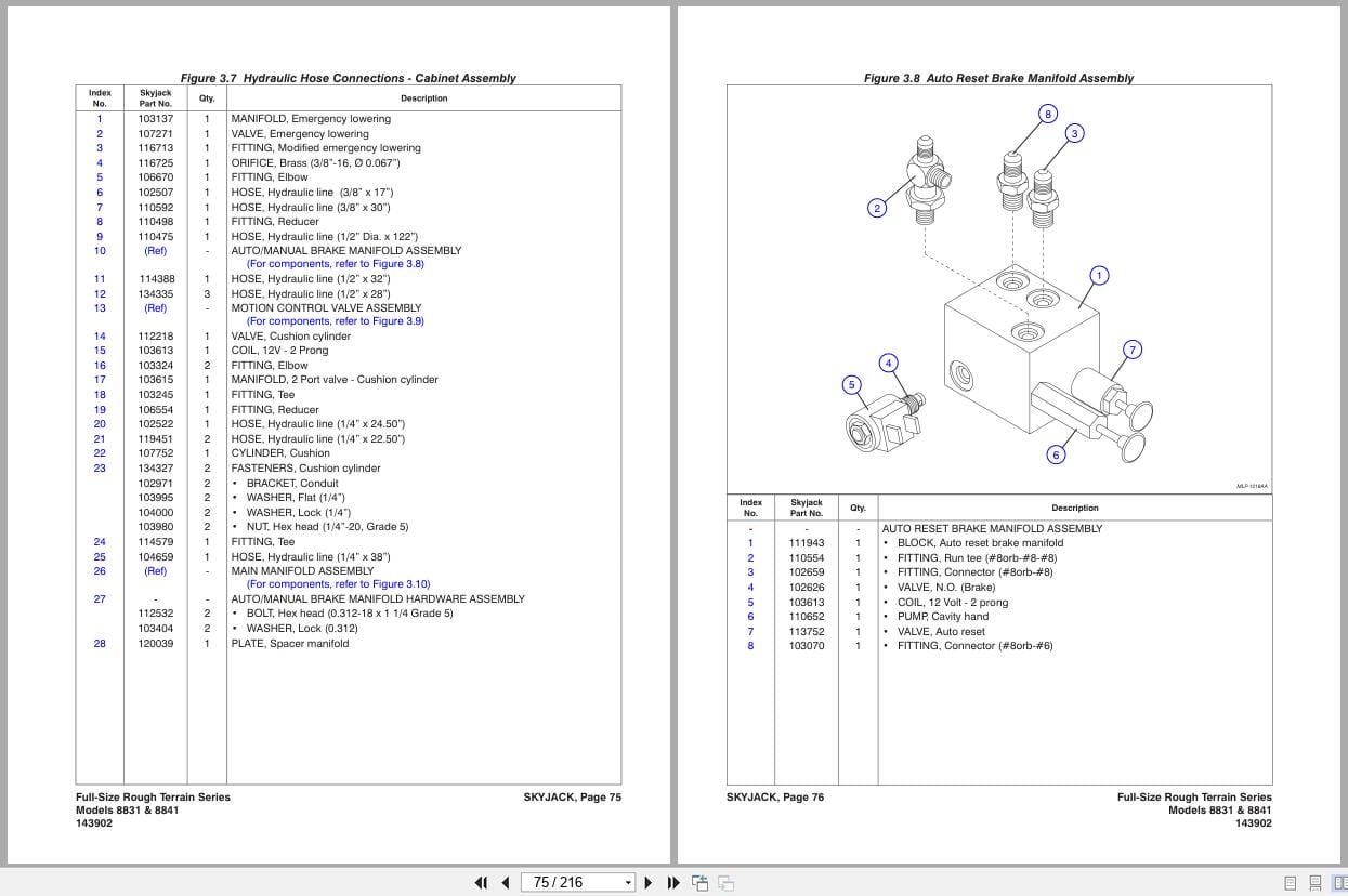
Figure 3.7 Hydraulic Hose Connections – Cabinet Assembly
Figure 3.8 Auto Reset Brake Manifold Assembly
Figure 3.10 Main Manifold Assembly
Figure 3.11 Base Control/Electrical Panel Assembly
Figure 3.12 Base Control/Electrical Panel Harnesses
Figure 3.13 Base Control Console Assembly
Axle Related Parts
Figure 4.1 Front Idle Axle Assembly (For 2-wheel Drive Aerial platforms)
Figure 4.2 Front Axle Hardware Assembly – All Wheel Drive Option (Cushman Axles)
Figure 4.3 Front Axle Assembly – All Wheel Drive Option (Cushman Axles)
Figure 4.4 Front Axle Assembly (Axle End) – All Wheel Drive Option (Cushman Axles)
Figure 4.5 Front Axle (Differential Assembly) – All Wheel Drive Option (Cushman Axles)
Figure 4.6 Front & Rear Axle (Wheel Hub Assembly) – All Wheel Drive Option (Cushman Axles)
Figure 4.7 Front Axle (Axle Shaft Assembly) – All Wheel Drive Option (Cushman Axles)
Figure 4.8 Steer Cylinder Assembly (4WD / Cushman Front Axle – 4WD) (Cushman Axles)
Figure 4.9 Front Axle Assembly (For 4-wheel Drive Aerial platforms) (Dana Axles)
Figure 4.10 Front Drive Axle Assembly – 4-wheel Drive (Dana Axles)
Figure 4.11 Steer Cylinder Assembly (Dana Axles)
Figure 4.13 Drive Motor Assembly
Figure 4.12 Drive Shaft Assembly
Figure 4.14 Center Drive Assembly
Figure 4.15 Rear Axle Assembly – (Cushman Axles)
Figure 4.16 Rear Axle (Differential Assembly) – (Cushman Axles)
Figure 4.17 Rear Axle (Brake Assembly) – (Cushman Axles)
Figure 4.18 Rear Drive Axle Assembly (Dana Axles)
Figure 4.19 Disc Brake Assembly (Dana Axles)
Figure 4.20 Disc Brake Cylinder Assembly (Dana Axles)
Engine Related Parts
Figure 5.1 Engine Roll Out Tray & Cover Assembly
Figure 5.2 Engine Control Panel
Figure 5.3 Engine Tray Lock Assembly
Figure 5.4 Diesel Engine Assembly (Kubota Diesel Engine D1305)
Figure 5.5 Diesel Fuel System (Kubota Diesel Engine D1305)
Figure 5.6 Kubota Diesel Fuel Engine Harness
Figure 5.7 Air Intake Assembly (Kubota Diesel Engine D1305)
Figure 5.8 Hydraulic Pump Assembly
Figure 5.9 Exhaust Manifold Assembly (Kubota Diesel Engine D1305)
Figure 5.10 Engine Roll Out Accessories (GM Dual Fuel Engine)
Figure 5.11 Dual Fuel Engine Assembly (GM Dual Fuel Engine)
Figure 5.12 Bell Housing Assembly (GM Dual Fuel Engine)
Figure 5.13 Engine Interface Harness (GM Dual Fuel Engine)
Figure 5.14 Dual Fuel Hose Assembly (GM Dual Fuel Engine)
Optional Equipment
Figure 6.1 Hydraulic Outrigger Option – Hydraulic Hose Connections
Figure 6.2 Hydraulic Outrigger Option – Leg Assembly
Figure 6.3 Hydraulic Outrigger Option – Cylinder Assembly
Figure 6.4 Hydraulic Outrigger Option – Manifold Assembly
Figure 6.5 Hydraulic Outrigger Option – Electrical Panel Assembly
Figure 6.6 Hydraulic Outrigger Option (Auto level) – Electrical Panel Connections
Figure 6.7 GP-108 Controller
Figure 6.8 Flashing Light Relay Harness
Figure 6.9 Outrigger/Hydraulic Generator Control Console Assembly
Figure 6.10 3500 Hydraulic Generator & Oil Cooler Option
Figure 6.11 12kW Hydraulic Generator & Oil Cooler Option
Figure 6.12 Hydraulic Generator & Oil Cooler Assembly
Figure 6.13 12kW Generator Mount & Breaker Box Assembly
Figure 6.14 Hydraulic Connections – 12kW Generator
Figure 6.15 Hydraulic Valve Assembly – 12kW Generator
Figure 6.16 Welder Option (ANSI/CSA)
Figure 6.17 1500W Inverter Option
Figure 6.18 Load Sensing Components (CE)
Figure 6.19 Air Hose to Platform Option
Figure 6.20 Work Light Option
Figure 6.21 Platform AC Outlet
Figure 6.22 Scissor Guard Option
Labels
Figure 7.1 Label Kit
Figure 7.2 Labels And Nameplates – Misc
Figure 7.3 Labels And Nameplates – Control Console Assemblies
Figure 7.4 Labels And Nameplates
Figure 7.5 Labels – Outrigger
Tables
Table 1.1 SJRT Scissor Fluids
REALEASE :
REALEASE :
REALEASE :
REALEASE :

REALEASE :
30.05.2020
REALEASE :
30.05.2020
REALEASE :
REALEASE :

REALEASE :
REALEASE :
REALEASE :
REALEASE :
REALEASE :
REALEASE :
REALEASE :
REALEASE :
 Automotive - Heavy Equipment - Truck & Bus - Forklift - Crane